
Installation manual


Windsor 500 Installation Manual - Issue C
-
15
-
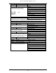
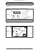
Main Control Unit
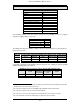
PCB Connections
The main PCB connectors are shown below. Each connector terminal is described in the
connection table. When connecting cables to the Windsor main control board it is essential to
avoid routing the cables under or over the board.
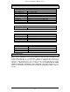
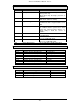
Connector Function Terminals
CON 1 Bell Tamper 1,2 Normally closed loop
CON 2 Battery monitor 1 12v
2 Battery charging (Red)
Refer to the battery monitor board 3 Battery present
7
(Amber)
section of this manual. 4 Mains present (Green)
CON 3 Internal Serial Bus PCB 1
Refer to ISB links LK5, LK6 & LK7
CON 4 STU
Refer to programming manual for PIN functions.
CON 5 Internal Serial Bus PCB 2
Refer to ISB links LK5, LK6 & LK7
CON 6 Serial Port 1 +12V
2 TXD
Refer to RS232 level shifter PCB section in this
3 RXD
manual.
4 RTS
5 CTS
6 DTR
7 DSR
8 DCD
9 RI
10 No Connection
11 No Connection
12 +5v
13 No Connection
14 0v
15 No Connection
CON 7 STU
Refer to programming manual for PIN functions.
CON 8 Internal Serial Bus PCB 3
Refer to ISB links LK5, LK6 & LK7
CON 9 UI Bus (keypads) 1 +12V
2 Clock
PIN 1 is protected by fuse 2.
3 Data
4 0V
CON 10 DGN Bus (concentrators) 1 +12V
2 Clock
PIN 1 is protected by fuse 3.
3 Data
4 0V
The screen terminal should be connected to
earth.
5 Screen(optional)
7
The battery present LED will only function if the panel is programmed to test the battery.