
Installation manual


Windsor 500 Installation Manual - Issue C
-
14
-
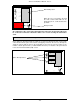
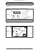
Main PCB position
When the case is mounted to the wall
the main control board PCB can be
fitted using the 11 screws and washers
provided.
Battery Position
On completion of the control panel mounting and connection, the lid earth cable must
be connected. Connection should be made to the screw securing the transformer
earth.
Main Control Unit
Option Boards
Before fitting an optional board fit the stand-offs to the board. Push the board over the main
control board connector pins and screw the self-tapping screws into the rear case through the
stand-offs. Ensure that the LK2 on the main PCB is moved to the correct position for the
number of fitted option boards (see Main PCB Connections). For details of the option board
refer to the Internal Serial Bus (ISB) section.
Option Board positions
1
2
3