
Installation manual


Windsor 500 Installation Manual - Issue C
-
13
-
Main Control Unit
Main Control Unit
Installation
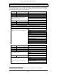
The Windsor control panel is supplied with a spares bag containing the following items;
• Case tamper tube (70mm) and spring
• Off the wall tamper plug, switch and spring
• Fuse 630mA
• Battery lead
• Mains cable clamp and two No 6 x 3/4” screws
• Cover earth wire assembly and M4 nut
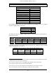
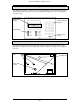
Conduit points
Trunking points
There are three 20mm conduit
knockout positions as indicated. The
required cable entry point(s) should be
knocked out from the inside prior to
mounting the case.
There are 4 trunking knockouts, 2 at
the top and 2 on the bottom edge of the
case. These can be knocked out from
either side.
Fixing holes
Mark the fixing positions shown and
secure the rear case to the wall using
3 suitable screws.
Off the wall tamper position