
Installation manual


Windsor 500 Installation Manual - Issue C
-
12
-
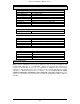
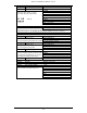
System Components
Current Consumption
Current Consumption (mA)
Control Board 60
2
Keypad 20
3
Keypoint 30
4
Inova Cardpoint 50
5
External concentrator 15
Internal 4 point concentrator 50
Internal 8 point concentrator 30
TX Communication PCB 30
Relay Output PCB 160 (All relays on)
SmartDial 30
Daughter Board 15 (all LEDs off)
Excalibur Switch Unit 5
Level Shifter PCB 20
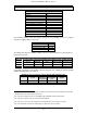
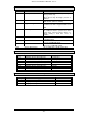
The following example shows the average system current (excluding sensors) for a typical
system at a supply voltage of 13.7 volts.
Control Unit 60 mA
1 Keypad 20 mA
1 Keypoint 30 mA
3 Concentrators (Ext) 45 mA
TOTAL 155 mA
The table below shows the available auxiliary current for various battery sizes using the above
typical system current.
24 hour battery re-charge time with a minimum 8 hours standby
Battery Size Ave. 24hr recharge
current
System current
maximum
Available backup
period
Windsor current
(example system)
Available Current
(for sensors etc.)
6 Ah 600 mA 750 mA
6
8 hours 155 mA 595 mA
12 Ah 1.2 A 800 mA 15 hours 155 mA 645 mA
15 Ah 1.5 A 500 mA 30 hours 155 mA 345 mA
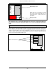
To obtain the maximum system backup current from a given size of battery for 8 hours standby
additional auxiliary PSUs are required.
Maximum system current for 8 hours backup with auxiliary PSUs
Battery Size Ave. 24hr recharge
current
System current
maximum for
8 hours backup
System current
from Windsor
PSU
Aux. PSU current
required
12 Ah 1.2 A 1.5 A 800 mA 700 mA
15 Ah 1.5 A 1.875 A 500 mA 1.375 A
2
The control board current does not include the battery monitor LED current. Each battery monitor LED
will add 10mA to the total control board current.
3
This is the basic keypad current. The backlighting will add 80mA and the buzzer 25mA.
4
This is the basic keypoint current. The buzzer will add 25mA
5
This is the quiescent current. The maximum current with the door unlock relay on is 90mA.
6
This is the maximum current that a 6 Ah battery can provide for 8 hours backup.