Windsor 500 Installation Manual Issue C
Windsor 500 Installation Manual - Issue C Contents Contents ......................................................................................................... 2 CE Declaration ............................................................................................... 7 Mains...................................................................................................................................... 7 Mains Supply...........................................................................
Windsor 500 Installation Manual - Issue C Adding / Deleting Alarm Users....................................................................................... 25 Alarm Panel Interface Functions ....................................................................................... 25 User Authority.................................................................................................................... 26 Standard Access Card Operation .............................................................
Windsor 500 Installation Manual - Issue C Relay Card ........................................................................................................................... 37 SmartDial ............................................................................................................................. 38 Approvals .......................................................................................................................... 38 LED Status Indicators...................................
Windsor 500 Installation Manual - Issue C Exchange Voltage Monitoring ........................................................................................... 50 Line Current Sensing.......................................................................................................... 50 Line Blocked Detection ...................................................................................................... 50 Series Handset Disconnect..............................................................
Windsor 500 Installation Manual - Issue C Issue C .................................................................................................................................
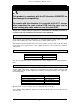
Windsor 500 Installation Manual - Issue C CE Declaration This product is compliant with the EC directive 89/336/EEC on electromagnetic compatibility. To comply with this directive it is essential to fit all 11 screws when mounting the main control PCB into the case and to avoid routing any cable under or over the main PCB. This product complies with the requirements of EN 60950. The following information is essential for the safe installation and operation of this equipment.
Windsor 500 Installation Manual - Issue C System Components A Windsor system comprises of 5 basic components; 1. The Windsor control unit, which processes all the alarm information from the detection points. Outputs are provided to operate sounders, strobe and communication devices. Configuration information is stored in battery backed RAM (Windsor Mk1, PC787) or EEPROM (Windsor 500, PC820). A printer port is provided on board. 2. User interaction with the system is via a two line 32 character backlit LCD.
Windsor 500 Installation Manual - Issue C System Components Order Codes Variant UK Standard 128 (English) UK Standard HS (English) Chubb Alarms 128 (English) Chubb Alarms HS (English) Generic Panel (no software) 128 French HS French 128 Italian HS Italian 128 Dutch HS Dutch 128 Czech HS Czech 128 Finnish HS Finnish 128 Slovak HS Slovak 128 Croatian HS Croatian 128 Hungarian HS Hungarian 128 Portuguese HS Portuguese Variant UK Standard Chubb Alarms French Italian Dutch Czech Belgian Finnish Lips Beveiligi
Windsor 500 Installation Manual - Issue C Communications SmartDial Super Windsor modem for 500 panel Windsor Modem for 700 panel (V23) Windsor Modem for GuardStation UK Windsor Modem for GuardStation EU GSR Remote Version 2 GSR Direct Version 2 Guardall Managed Reset PC software AV60 UK AV60 France AV60 microphone expansion PCB AV60 microphone 73460 73535 73606 73534UK 73534EU 73429 73537 72951 73582 73583 73584 73585 Windsor Product W Numbers Main PCB (PC820/1) STD UK 73411 Main PCB (PC820/2) EURO 73380
Windsor 500 Installation Manual - Issue C System Components Technical Specification Mains Input Mains fail detection Power supply voltage Low voltage detection Power fail detection Power supply output Load current Load current Standby battery Electrical 230V AC (+10% -15%) 50/60 Hz Loss of AC supply Normally +13.7V 11V DC 10.
Windsor 500 Installation Manual - Issue C System Components Current Consumption Current Consumption (mA) 2 Control Board 60 3 Keypad 20 4 Keypoint 30 5 Inova Cardpoint 50 External concentrator 15 Internal 4 point concentrator 50 Internal 8 point concentrator 30 TX Communication PCB 30 Relay Output PCB 160 (All relays on) SmartDial 30 Daughter Board 15 (all LEDs off) Excalibur Switch Unit 5 Level Shifter PCB 20 The following example shows the average system current (excluding sensors) for a typical system
Windsor 500 Installation Manual - Issue C Main Control Unit Main Control Unit Installation The Windsor control panel is supplied with a spares bag containing the following items; • • • • • • Case tamper tube (70mm) and spring Off the wall tamper plug, switch and spring Fuse 630mA Battery lead Mains cable clamp and two No 6 x 3/4” screws Cover earth wire assembly and M4 nut There are three 20mm conduit knockout positions as indicated.
Windsor 500 Installation Manual - Issue C Main PCB position When the case is mounted to the wall the main control board PCB can be fitted using the 11 screws and washers provided. Battery Position On completion of the control panel mounting and connection, the lid earth cable must be connected. Connection should be made to the screw securing the transformer earth. Main Control Unit Option Boards Before fitting an optional board fit the stand-offs to the board.
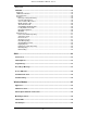
Windsor 500 Installation Manual - Issue C Main Control Unit PCB Connections The main PCB connectors are shown below. Each connector terminal is described in the connection table. When connecting cables to the Windsor main control board it is essential to avoid routing the cables under or over the board. Connector CON 1 Function Bell Tamper Terminals 1,2 Normally closed loop CON 2 Battery monitor Refer to the battery monitor board section of this manual.
Windsor 500 Installation Manual - Issue C Connector CON 11 Function Printer Serial output with 8 data bits, 1 stop bit and no parity.
Plug-on STU or Dialler Engineer UI UI bus Bell Tamper Sounder Strobe Loudspeaker Battery Monitor board Comm Port - 17 - Option boards EEPROM (config) EPROM Conc Line Printer Bus Fault Windsor 500 Installation Manual - Issue C AC Input Aux Power Battery
Windsor 500 Installation Manual - Issue C Main Control Unit Link LK1 Function Battery connect LK2 ISB LK3 Engineer Keypad LK4 Power-up set LK5 ISB LK6 ISB LK7 ISB LK8 Off the Wall Tamper Main Control Unit Fuse Fuse 1 Fuse 2 Fuse 3 Fuse 4 Fuse 5 Fuse 6 Fuse 7 mains Comments When fitted the panel can be powered up on battery power only. When fitted deep discharge protection is disabled. Fit the ISB link on LK2 if there are no ISB PCBs fitted.
Windsor 500 Installation Manual - Issue C User Interfaces Windsor can have up to 8 user interfaces connected on the keypad bus (CON 9) and an 8 engineer keypad connected directly to the main PCB (CON 17). User interfaces can be either an LCD keypad, a Keypoint or an INOVA Cardpoint. All user interfaces are connected to Windsor on a 4 wire bus. User Interfaces Cable Length The maximum length of cable for a single keypad is shown in the table.
Windsor 500 Installation Manual - Issue C User Interfaces Keypad The Windsor keypad has a 2 line by 16 character backlit LCD, a 15 button backlit keypad, 8 status LEDs and an electronic key socket as standard. All keypads are connected to Windsor on 4 wire UI bus. 2 x 16 character LCD backlit display 15 button backlit keypad Guardall 12:00 Status LEDs Electronic key socket Keypads Installation The keypad should be fixed to the wall through using the fixing holes provided.
Windsor 500 Installation Manual - Issue C Keypads Addressing All keypads are identified by a unique address which is set using links on the keypad PCB. The keypad addresses must be in sequence from 1 up to the maximum number specified in the System Size programming option.
Windsor 500 Installation Manual - Issue C User Interfaces Keypoint The Windsor keypoint has backlit set and unset buttons, 4 status LEDs and an electronic key socket as standard. All keypoints are connected to Windsor on 4 wire UI bus. Set and Unset backlit buttons Status LEDs Electronic key socket Keypoint Installation The keypoint should be fixed to the wall through using the fixing holes provided.
Windsor 500 Installation Manual - Issue C Keypoint Addressing All keypoints are identified by a unique address which is set using links on the keypoint PCB. The keypoint addresses must be in sequence from 1 up to the maximum number specified in the System Size programming option.
Windsor 500 Installation Manual - Issue C User Interfaces Inova Cardpoint The INOVA Cardpoint has set and unset buttons and 4 status LEDs as standard. All Cardpoints are connected to Windsor on 4 wire UI bus. The Cardpoint can be used as a normal access control unit and to set and unset Windsor. The normal guidelines for installing a standard Inova Access Controller should be followed.
Windsor 500 Installation Manual - Issue C Inova Hardware Wiring Details Refer to wiring diagram (Main Circuit Board) on Inova Installation instructions. 1. On the main terminal block, terminals 1-4 should be connected to the control panel user interface bus (CON 9 ). Terminal Terminal Terminal Terminal 1 2 3 4 +12V Clock Data 0v 2. Refer to detail B, Inova Installation Instructions (Door Strike Wiring).
Windsor 500 Installation Manual - Issue C Inova User Options User Authority Two types of access card (visually identical but programmed differently) can be distributed to users. Inova User Authority Standard Access Card Operation Holders of valid standard access cards will have normal access when the system is unset, but will be unable to gain access when the alarm panel is set.
Windsor 500 Installation Manual - Issue C Inova Cardpoint Commands Command Swipe Master Card # abcd # Suffix None Description Enter learn mode None #00# None #14# 1# Enter Programming mode in order to reset the reader (abcd is one of the two master reset codes) Exit Learn Mode/Exit Programming Mode Set door release time to 1 second Set door release time to 5 seconds (default) Set door release time to 5 seconds Set door release time to 5 seconds Add access card no. nnnnn Add alarm card no.
Windsor 500 Installation Manual - Issue C Concentrators All detectors are connected to Windsor via a concentrator input. There are two types of concentrator; an internal concentrator which is plugged onto the main PCB and external concentrator which is connected to Windsor on a 4 wire bus. Internal concentrators can have 4 or 8 inputs. External concentrators always have 8 inputs.
Windsor 500 Installation Manual - Issue C Concentrator Installation Daughter board pillars Trunking points Case fixing positions Rear tamper knockout Concentrator Addressing All concentrators are identified by a unique address which is set using links on the concentrator PCB. The concentrator addresses must be in sequence from 1 up to the maximum number specified in the System Size programming option. The total number of concentrators includes both internal and external types.
Windsor 500 Installation Manual - Issue C Concentrator Connecting Sensors The concentrator connections for a sensor depends on the type of concentrator. The connections are the same for both internal and external concentrator types. HS concentrators are connected in the same way as a an EOL type but both resistors are 8k2.
Windsor 500 Installation Manual - Issue C Concentrator Connector TB1 Connections Function Control Panel Bus The screen terminal should be connected to earth. PL1 Aux Power Output Outputs supplied via fuse 1 PL2 Circuit 4 Refer to diagram for EOL/NEOL connections.
Windsor Installation Manual - Issue C Vigil Concentrator The Vigil concentrator operates in the same way as a Windsor concentrator. The main difference is that a Vigil concentrator, when used in a Windsor system, can be addressed up to concentrator 16. The connections to the Vigil concentrator are also different and are explained in the following section. The Vigil concentrator (EOL and HS types) can be identified by the DIL switch used for setting the concentrator address.
Windsor Installation Manual - Issue C HS Concentrator The HS concentrator is functionally equivalent to the existing “Vigil” concentrator and may be used in a Windsor 500 or 700 system. The maximum concentrator address is 32 which allows systems of up to 256 circuits to be configured. On a Windsor 500 the maximum number of circuits is 128. The HS concentrator PCB is supplied either in a Windsor 500 concentrator plastic case (white plastic with screw on lid) or in a metal case.
Windsor Installation Manual - Issue C HS Concentrator Connecting Sensors On a HS concentrator the sensors are connected in the same way as an EOL type but both resistors are 8k2.
Windsor Installation Manual - Issue C HS Concentrator Connector TB1 Connections Function Control Panel Bus The screen terminal should be connected to earth.
Windsor Installation Manual - Issue C Internal Serial Bus The Windsor internal serial bus (ISB) can have up to 4 optional PCBs fitted. The Optional PCBs are either; • • • • SmartDial/SmartDial Plus 8 circuit Concentrator 8 channel TX or relay card AV60 audio verification card When an ISB option board is fitted the ISB link on the main PCB must be moved to the appropriate position. If this link is fitted incorrectly then all ISB option boards and all keypads will not function.
Windsor Installation Manual - Issue C Internal Serial Bus TX Card The Windsor ISB TX card has 8 programmable outputs. The default polarity is positive removed but this can be inverted in software. Programmable outputs Main PCB connector Internal Serial Bus Relay Card The Windsor Relay card has 8 programmable outputs. The default polarity is positive removed but this can be inverted in software. Each output has a NO and NC contact.
Windsor Installation Manual - Issue C Internal Serial Bus SmartDial SmartDial is a combined dialler/modem which connects to Windsor on the internal serial bus. SmartDial is fully programmable from a Windsor keypad and can share a telephone line with a telephone handset(s). Refer to the SmartDial instructions for the telephone line connections and features. The PCB layout shown is for a SmartDial/SmartDial Plus but the terminals are in the same position in a SmartDial Super.
Windsor Installation Manual - Issue C SmartDial Panel Selection SmartDial Super is a universal product, interchangeable on all Windsor panel variants by a simple link selection. LK1 = Removed for Windsor 300 panels LK1 = Fitted for Windsor 500 and 700 panels SmartDial SmartDial Features Features Exchange Voltage Monitoring As a protection against a cut line or telephone line fault, the nominal supply voltage from the telephone exchange is continuously monitored.
Windsor Installation Manual - Issue C If Handset and Line blocked are both programmed then line blocked and exchange voltage monitoring will only be reported to the panel when the system (all areas) is set. Connecting handsets in any configuration other than the method stated above (such as parallel connection) will invalidate BABT (UK PTT) approval. SmartDial Features DTMF and Pulse dial The communicator is capable of both DTMF and Pulse (loop disconnect) dialling of the programmed telephone numbers.
Windsor Installation Manual - Issue C SmartDial Alarm Protocols SmartDial Protocols Fast Format Alarm Reporting In the fast format alarm format alarm data is represented by 8 channels. When any channel changes state, the communicator is triggered to initiate a call to the programmed central station.
Windsor Installation Manual - Issue C SmartDial Protocols Point ID Reporting This is an alarm reporting protocol which allows additional data to be transmitted to the central station without resorting to a modem format. It uses DTMF transmission with a message content significantly different from standard fast format protocols. With normal alarm reporting, a single alarm code is transmitted to the central station when one or several circuits have been triggered.
Windsor Installation Manual - Issue C Internal Serial Bus AV60 For Link and Switch options see notes 4 5 500mA 250V 20mm ISB Socket Telephone Socket Tamper Broadcast Talkback Sw Live Channels 1 - 8 (12V - IN - 0V) AV60 Connections Connection Audio 1-8 SW Live Talkback Broadcast Tamper Function 12v, +ve feed to microphone IN Audio connection to microphone 0v, -ve feed to microphone LED enable to microphone (common for all microphones) Audio to Talkback unit Audio to Broadcast unit tamper connecti
Windsor Installation Manual - Issue C AV60 Access PIN Code To program the access PIN code; 1. Connect a telephone handset with DTMF capability to the telephone socket of the AV60. 2. Press #7 on the handset. 3. Enter the 4 digit access code. 4. Press * to terminate the access code. 5. Press #3 to exit. If the control panel is de-powered the access PIN code must be re-entered. AV60 Command Functions All commands from the alarm receiving centre are entered using a DTMF telephone handset.
Windsor Installation Manual - Issue C Windsor Modem There are 2 variants of the Windsor modem; • W73535 Windsor 500/700 panel modem • W73534 Windsor Receiver modem for GuardStation There is only one version of the Windsor modem software for all target countries. The Windsor modem software has 3 pre-configured profiles which can be selected by using the ATZn command. The profile usage is shown in the table. The profile contents are detailed in the Windsor modem defaults section.
Windsor Installation Manual - Issue C The Windsor modem connects to the Windsor 500 or 700 with a ribbon cable. On a Windsor 500 it connects directly to the comms port without an RS232 interface adapter. DC input Control panel interface Status LEDs Audio inputs PTT Connections TB series connected apparatus ‘B’ wire EPROM B PSTN ‘B’ wire BC spur point only. For series apparatus which use bell common GND spur point only.
Windsor Installation Manual - Issue C Modem Terminal Block Ancillary Equipment BC BC Blue Wire of equipment (and blue from pin4 of TE PLUG ) Red Wire of equipment TB TB B B GND GND Green Wire of equipment (and green from pin4 of TE PLUG ) A A TA White Wire of equipment TA Figure 1.2 2. Windsor Modem Receiver (W73534) Connection to the telephone network is made via the standard UK TE Plug.
Windsor Installation Manual - Issue C Standard UK TE PLUG 1 n.c. 2 White Viewed from underside (pin connections visible ) 3 Green " TE PLUG(BS6312 part1)" 4 Blue 5 Red 6 n.c. Figure 1.4 International RJ11 Plug RJ11 PLUG 1 2 3 4 5 6 Figure 1.5 - 48 - Viewed from underside (pin connections visible ).
Windsor Installation Manual - Issue C Windsor Modem Mounting Positions The Windsor modem can be mounted in 2 ways in a Windsor 500; either on PCB mounted pillars or on above one of the ISB PCBs. In a Windsor 700 the modem can only be fitted above one of the ISB PCBs.
Windsor Installation Manual - Issue C Windsor Modem Features Country Number of re-attempts 1st-2nd call attempt delay (seconds) subsequent call attempts delay (seconds) Windsor Modem Features Call Attempts UK 2 7 NL 14 7 IT 3 7 FRA 4 8 IRL 3 7 BEL 3 7 FIN 3 7 SA 3 7 AUS 3 7 62 62 62 8 62 62 62 62 62 Exchange Voltage Monitoring As a protection against a cut line or telephone line fault, the nominal supply voltage from the telephone exchange is continuously monitored.
Windsor Installation Manual - Issue C Windsor Modem Features DTMF and Pulse dial The communicator is capable of both DTMF and Pulse (loop disconnect) dialling of the programmed telephone numbers. Dialling will only commence in the presence of a valid proceed indication (dial tone) and may employ Timed Break Recall.
Windsor Installation Manual - Issue C Windsor Modem Command ATE0 ATV1 ATV0 ATB0 AT Commands Modem action ATP ATT ATA *NO ACTION *NO ACTION *NO ACTION Adaptive call originate/answer and return to 2400 baud command mode Force V23 HDX and return to 2400 baud command mode 1200 & 300 baud FSK can be achieved using the %B command (default) Force V23 HDX and return to 1200 baud command mode 1200 & 300 baud FSK can be achieved using the %B command Set serial port to 1200 bps Set serial port to 2400 bps Set seri
Windsor Installation Manual - Issue C Command ATDRxxxx\r AT&D3 AT&RI AT&CD AT&TBR AT&BD AT&CC AT&CH ATZn ATZnCC Modem action Modem response 2 : ADEMCO Contact ID 9 : ADEMCO Superfast Dial telephone number with double call timer enabled.
Windsor Installation Manual - Issue C Windsor Modem RX Variant The front panel of the Windsor RX modem has 2 RJ11 sockets for a telephone handset connection and the incoming PTT line and 12 status LED indicators. The rear panel of the Windsor RX modem has a 9 way D type RS232 connection and a DC supply input. A suitable RS232 cable for connection to the PC host must be used (not supplied).
Windsor Installation Manual - Issue C Windsor Modem Defaults The Windsor modem has 3 sets of defaults which are shown in the table. The appropriate profile can be selected using the ATZ command.
Windsor Installation Manual - Issue C SmartComm SmartComm is a combined dialler/modem which connects to Windsor on the communications port. SmartComm is fully programmable from a Windsor keypad and can share a telephone line with a telephone handset(s). SmartComm can be used to signal alarms in ADEMCO fast format. As a modem SmartComm operates at 1200 baud and can be used for downloading from a remote PC. To install the SmartComm PCB in Windsor it must be mounted on the pillars provided.
Windsor Installation Manual - Issue C RS 232 Interface PCB The Windsor RS232 Interface board connects to the communications port, CON 6, of the main PCB. The function of the RS232 Interface board is to convert the TTL voltage levels on the main PCB to the RS232 voltage levels. An RS232 Interface board will be required if you are connecting Windsor to a PC, modem, PAKNET or X25 pad. It is not required if you are connecting to SmartComm or Pacom.
Windsor Installation Manual - Issue C Printer Port A PC may be connected directly to the printer port if the panel is fitted with version 3.00 or later software. If the main PCB printer connection (CON 11) is being used refer to the PCB connections section of this manual. If the panel printer cable assembly is being used the 7 pin DIN connections are shown below.
Windsor Installation Manual - Issue C Light Control System Windsor can have up to 4 light zones programmed. Only 2 types of circuit can be programmed to operate in a light zone, Excalibur daylight (Exc-D) and Excalibur trigger (Exc-T). There is no connection between a Windsor area and a light zone. Each light zone has a programmable TX output which can be controlled by a trigger circuit, a daylight level, manually, by a timer or by an alarm event.
Windsor Installation Manual - Issue C Light Control System Mains Switch Unit The Windsor mains switch unit (MSU) has 2 independently programmable relay outputs each capable of switching a 2kW load. Up to 8 MSUs can be independently addressed and, if required, more than one MSU can be programmed with the same address to give multiple outputs controlled by the same programmable function.
Windsor Installation Manual - Issue C Mains Switch Unit Wiring Guidelines The following guidelines are supplied in order to ensure the safe installation of the mains switch unit. Failure to follow these guidelines may create hazardous electrical conditions for the system user. Approval of the apparatus may also be invalidated if, as a result, it then ceases to comply with the standards against which approval was granted.
Windsor Installation Manual - Issue C If Output 2 is to be used, then the wire which is coloured brown must be connected to the other terminal labelled Output 2 which is not used for the mains supply. Mains Switch Unit Precautions Precautions must be taken to prevent electrical contact between all mains voltages (including mains wiring and mains connector block) and low voltage circuitry (including data bus wiring and data bus connector block).
Windsor Installation Manual - Issue C Change History Change History 1. 2. 3. 4. 5. 6. 7. Added muti-level contents section. Added SmartDial Super details and SmartDial features. Added new table of concentrator order codes. Added battery monitor LED colours to main PCB connections table. Added new RS232 interface PCB number. Added connections column to the Vigil concentrator outputs table. Added Inova programming options. Change History 1. 2. 3. 4. Issue B Issue C Added Windsor modem section.
Guardall Limited Lochend Industrial Estate Newbridge Edinburgh EH28 8PL Scotland Part No.