
Installation manual

Alarm is produced, this can be treated as an ALARM CONFIRMATION
signal or SECOND ALARM.
e.g. To transmit A CONFIRMED ALARM signal using REDCARE or
DualCom set up the alert alarm type and response to trigger an output
and connect it to trigger a Channel 3 (intruder) on the STU and the
intruder Alarm type can be used to trigger a Channel 7 (Confirmed
Alarm). Please refer to above italics for notes on restoring these
outputs on disarm.
Refer to NACOSS Codes of Practice NACP 14 for design guidance on the
use of ALARM CONFIRMATION systems.
OP6
2K7ohm
pull-up
resistor on
each output
12V
Comfort
Main PCB
OP5
RedCARE
BLU STU8
1
2 PA
3 INTRUDER
4 O/C
5 ABORT
6 CONFIRM
OP4
12V
OP3
OP2
12V
OP1
12VF
COM
12V
0V
+12V
ON
DIL switch
1 2 3 4 5 6 7 8 9 0
ALERT
PA
INTRUDER
O/C
ABORT
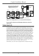
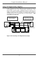
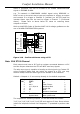
Figure 2.16 - Confirmed Alarms using a STU
Note: BLU STU 8-Channel
Each output must have a 2K7 pull-up resistor connected between +12V
and the output otherwise the STU will NOT send any signals.
The alert zone type is capable of sending a silent signal via ‘Contact ID’
using Comfort’s dialler and can switch an output to a STU, you may
wish to modify the alert alarm type to be audible in this instance.
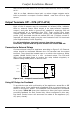
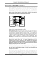
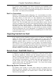
Default = Outputs 1- 8 are set-up already in the default responses.
77Restore outputs 1-6
when system unset
Sec. Off Mode or
System Unset
1-6
11Intruder as Confirmed16
9
Abort
20
5
7System Set 194
5
Intruder or Alert
(1,11,22) or 6
3
3Panic / Duress9 & 22
1
Fire
12
1
ResponseAlarmApply to Alarm
Types
Output
No.
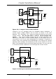
The response for restoring outputs 1-6 can be written as follows:
74,2,74,4,74,6,74,8,74,10,74,12,255 and requires 3 lines. Once written
insert the response number into Response 77 preceded by action code
74.
Comfort Installation Manual
49