
Installation manual

NOT to the wire that returns to the zone COM terminal, which is already
at 0V .
‘GJD XL or Opal’ detectors have both -ve alarm trigger outputs and a
built-in photocell -ve output. Comfort ‘default ’ uses zone 13 for a light
sensor.
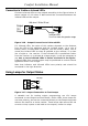
Output Terminals OP1 - OP8 (JP11-JP14)
Each of the 8 outputs may be connected to infrared LEDs, indicator
LEDs or external relays. Each output is an open-collector transistor
output ( and pulls down to ground 0V) capable of supplying 200 mA
and protected by a resettable fuse (F2). Total current from these
outputs together with the switched (S12V) and unswitched auxiliary
power (12V) terminals should not exceed 500 mA. If higher current is
required, an external supply may be used instead of the 12V terminals
(see Supplementary Power Supplies).
(( For UL installations, the total current from Alarm output
terminals, outputs and aux power should not exceed 500 mA
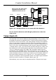
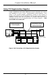
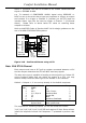
Connection to External Relays
Connect external relays for appliance according to Figure 2.13. External
relays should be connected between the 12V terminal and the output
terminal. They should be located near to or within the enclosure. Relay
module (Model RLY01) has 4 x 12V on-board relays. The CPU and
REP’s have threaded posts to receive the relay boards singularly or
stacked using metal pillars in various sizes.
N/O
N/C
COM
OUTPUT
12V
OUTPUT
+
-
Appliance Relay
Figure 2.13 - Output Connection to a Relay
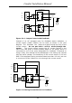
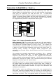
Using AC Relays for Feedback
To provide the user with confirmation of the appliance’s actual On or Off
condition use a 2 way switch and a feedback relay or current sensor, as
shown in the figure below. The feedback relay contacts are connected
to an input. Table 26 gives the Locations to enter the Input numbers
providing feedback for each Control Key. When configured in this way,
the Home Control menu will announce the state of the appliance (on,
off, open, closed).
Comfort Installation Manual
43