
Installation manual

4K7
CCT
TAMP
PWR
+
-
Zone Input
Terminals
Double
EOL
Position
JZ8
3 2 1
2K7 = Red,
Violet, Red
4K7 = Yellow,
Violet, Red
Z8
COM
Z7
S12V
0V
12V
JZ7
3 2 1
4K7
CCT
TAMP
PWR
+
-
4K7
CCT
TAMP
PWR
+
-
2K7
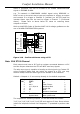
Detector 1Detector 2Detector 3
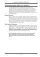
RELAY 'PULSE' WILL RESET SHOCK
AND SMOKE DETECTORS USING
ARMING RESPONSE IN LOC 1850
Comfort Main CPU
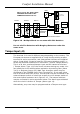
May need to use a terminal block to joint the zone wire between detectors
LNK LNK
Single cable
returns to the
panel zone
Output
Terminals
OP8
12V
OP7
OP6
12V
OP5
RLY01
Figure 2.9 - Multiple Shock on one zone with EOL Resistors
(( Do not mix Fire Detectors with Burglary Detectors under the
same zone.
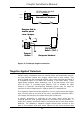
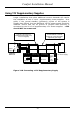
Tamper Input (J4)
The terminal J4 is used in different ways depending on the country. The
European Versions are supplied with a 3-way block providing a spare
terminal for series connection, and International Versions are supplied
with a 2-way block. J4 can be used for CPU case protection and/or in
series with External Audible Siren connection. (0v and Tamper Return).
This is a 24 hour monitored tamper input and will caused a full alarm
(‘Tamper Alarm’ Type 11) if the circuit is broken during any mode. You
can break the circuit without alarm activation by entering User (Menu
3,4,2) or Engineer (menu 8,2) Walk Test. A tamper switch may be
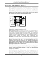
connected to the TAMPER input (2 pin Terminal J4). If not used, short
the J4 terminal block with a wire. This terminal may be connected to an
external tamper switch of a bell box as well as to the tamper switch of
the control panel enclosure as in Figure 2.12. The tamper switches
may be connected in series as shown below. The Alarm type activated
when the circuit is broken is Tamper (Alarm type 11).
Alternatively, any zone may be programmed as a Tamper zone type.
Comfort Installation Manual
41