
Installation manual


To provide a ‘global tamper’ protection for these types of zone
configurations, assign one zone as a ‘tamper’ zone type 20 and connect
all zone wiring tampers in series to this tamper zone.
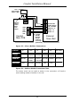
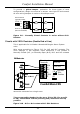
JZ1-8
3 2 1
Zones must be
normally closed.
Shunt on pins 1 & 2.
(Near to terminals)
Zone
COM
Zone
Tamper Tamper
Alarm Alarm
Figure 2.8 - Normally Closed Contacts in series without EOL
Resistor
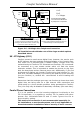
Circuits with 2 EOL Resistors (Double End of Line)
This is applicable for UL Grade A Household Burglar Alarm System
units.
Wire zones according to Figure 2.10 for N.O and N.C contacts. The
Zone Settings in the Engineer menu determine if the contact is
Normally Closed (N.C.) or Normally Open (N.O). N.O. and N.C contacts
cannot be connected on a single zone.
(( The corresponding header for the zone, JZ1 to JZ8 (for zone Z1
to Z8) should have a shunt (shorting link) inserted in the top
position.
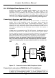
Figure 2.10 - N.C or N.O contact with 2 EOL Resistors
Comfort Installation Manual
39
Zone Input
Terminals
Double
EOL
Position
JZ8
3 2 1
2K7 = Red,
Violet, Red
4K7 = Yellow,
Violet, Red
Z8
COM
Z7
S12V
0V
12V
JZ7
3 2 1
4K7
ALM
(N.C. or N.O.)
TAMP
PWR
+
-
2K7
PIR Detector
Comfort Main CPU