
Installation manual


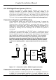

normal extension phone. In this case, the system should be connected
to an extension which is designated to be connected to one of the
exchange lines in the event of a power failure. If the system is
connected as an extension of a PABX and it is required to dial a number
to obtain an outside line, program the PABX Option in the Engineer
Menu (7,2), and the PABX Key (7,2,1) to the prefix to be dialled to get
an outside line (usually 9 or 0). Do not include the 9 or 0 in the
telephone numbers programmed for dialout. In the event of a
power failure and a dialout is required, the system will dial the numbers
without the prefix, as it assumes that it is connected to an extension
that has direct access to the exchange line during a power failure.
Connect the PABX to the same electrical circuit as the system so power
failure of the PABX can be monitored. Other extension phones can
access the system by dialling the extension to which Comfort is
connected.
(( The system must not be connected as an extension of a PABX
system for UL- approved or monitored installations, as it may
not be possible to seize the telephone line to dial out during an
alarm. Also it would not be possible to detect telephone line
cut on the incoming exchange lines.
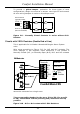
Zone Input Terminals Z1- Z8 (JP3 - JP6)
Each zone may be wired as Normally Closed (NC) or Normally Open
(NO). Any unused zones should either be programmed as Zone Type 0
with the zone inputs left open and corresponding zone header (JZ1 to
JZ8) with a shunt (shorting link) in the position close to the terminal
blocks for Non EOL resistor or left programmed but with a wire loop in
the zone terminal.
(( Normally Open and Normally Closed contacts cannot share a
zone.
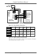
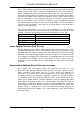
Circuits without EOL Resistor
This is applicable for UL Grade B Household Burglar Alarm Systems
units
Wire zones according to Figure 2.8 for Normally Closed Contacts and
Figure 2.9 for Normally Open Contacts.
The corresponding 3-pin header for the zone, JZ1 to JZ8 (for
zone Z1 to Z8) should have a shunt (shorting link) inserted
nearest the terminal block (2 to 3) when no EOL Resistor is
used .
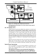
In this configuration, the system does not differentiate between a
contact open, open circuit wiring (tamper) condition, or contact closed
and short-circuit wiring (fault) condition. The Zone Settings in the
Engineer menu determine if the contact is Normally Closed (N.C.) or
Normally Open (N.O.). N.O. and N.C contacts cannot be connected on a
single zone.
Comfort Installation Manual
38