
Installation manual


Telephone Connections
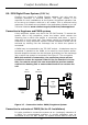
Single Line Telephone Connection
Comfort must be connected in series between the incoming telephone
line and the house phones using solid core telecom cable and not
stranded alarm cable. Use the proper jointing IDC (Krone) tool for
making connections rather than a screwdriver. Connect the incoming
telephone line to the TEL IN Terminal Block. Connect the telephone
wires going to the house phone(s) to the TEL OUT Terminal Block. The
system will work with any tone-dialling telephone. For retrofit
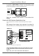
applications where the panel is sited away from the incoming telephone
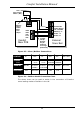
line, a single cable (6 or 8 core solid) can be used to divert the
telephone line through the Comfort panel using only 5-cores (see fig
2.5). A ringer module (RGR01 or 02) should be used if the doorbell and
reminder messages are required to ring the telephone.
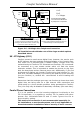
Telephones, facsimile machines and other telecommunications
equipment may be connected to the Telephone OUT socket.
(( Do not connect any other equipment between the incoming
telephone line and the control panel. Also, do not connect any
other telephone equipment including fax machines and PABX in
parallel with the control panel. Violating the above conditions
may prevent the control panel from seizing the telephone line
to dial out during an alarm condition. If telephone equipment
are connected in parallel with the system, a Phone Trouble
condition will be generated if the parallel equipment is used.
House Extensions
4 REN Max.
NOTE
A Master Socket MUST be
used on TEL-OUT to ensure
that internal phones ring
Comfort
CPU
TEL
IN
TEL
OUT
5
MJ1
MJ2
3
2
1
4
5
6
3
5
2
2
5
2
Comfort
Master Socket
3 2 5
A = 5
B = 2
C = 3
ringer
BT Line IN
Master Socket
NT5
Secondary
Sockets
Figure 2.5: UK Retrofit Telephone Connection example
Comfort Installation Manual
35