
Installation manual

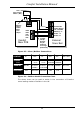

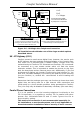
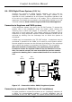
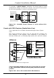

Figure 2.3 - Siren /Bellbox Connections
Figure 2.4 - Bellbox Model Connection Chart
The above chart can be used to assist in the connection of Comfort
some leading makes of bellbox in the UK.
Comfort Installation Manual
34
SPK-
0V - TR
Remove
Link to
enable
panel
case-
tamper
12VF
Comfort
Main PCB
STR-
SRN+
SRN-
External
Siren/ Bell
0V Hold Off
Tamper Return.
12V + Hold Off
SRN Trig - ve
Strobe - ve
Strobe +ve
1K-Ohm
Pull-Up
Resistor
may be
needed if
siren rings
permanently
Panel Tamper
Switch - (N.C.)
COMFORT TR 12VF 0V SRN- STR- NOT USED
GARDTEC TMP RET 12V SUPP+ 12V SUPP- BELL SW- STROBE- BELL SW+
STROBE+ F TMP FEED
CEQURA A/T RET SIG HOLD OFF HOLD OFF SIREN STROBE SET
(CQR) +12Vdc -12Vdc TRIGGER TRIGGER
VENTCROFT
RTN HOLD OFF+ HOLD OFF- TRG STB