
Installation manual

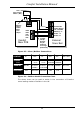

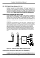

Speaker and Strobe (JP10)
Connect a strobe light to the 12VF and STR - outputs if needed.
Observe the polarity. For UL Installations use a UL approved strobe, eg
Wheelock LS1-12-VFR. In the event of an alarm, the strobe is turned on
until the system is disarmed. The Strobe and speaker terminals have a
combined current limit of 1 A, protected by a resettable fuse (F3)
Connect an 8 ohm 5W (minimum) speaker to the SPK- and 12VF
outputs. Polarity is not important for a speaker.
(( The backup battery must be connected for the Siren to work
properly.
(( When the system is running on battery alone, full siren sounds
will not sound through keypads to preserve power, this is not a
fault .
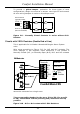
Siren / Bellbox Connections (JP9)
Some ‘supervised’ bell boxes may ‘sound’ as soon as they are
connected. If so, they may need a pull-up resistor (1K-ohm) placing
between the +12V hold-off and their negative ‘trigger’ terminal, this
should be inserted at the bellbox end. Should you wish to work on the
bellbox connections or open the control panel, you can immobilise the
system from causing a tamper alarm by entering Engineer Test Mode
via Eng. Menu 8,6,1 for ON. Upon de-selecting this option 8,6,0 for Off,
the system will enter ‘Security Check Mode’ and will report any faults
through the keypad. ‘Tamper Alarm 1’ means the Panel Tamper or
Bellbox Tamper switch or Connections are open or incorrect.
SRN- This is the bell trigger output which can be programmed for SAB
or SCB (Siren Reverse) operation as follows: Select Siren Reverse
Option ‘ON’ for SCB in Engineer Menu 4,3. SAB, Siren Reverse
OFF=Default.
SAB: SRN- will switch to 0V on alarm and will provide a maximum of
700mA.
SCB: SRN- will provide a negative hold off (500mA), which is removed
on alarm.
The Tamper Connections offer 24 hour protection. Breaking the tamper
circuit will cause a Tamper Alarm signal on the speaker and can cause a
dial out to programmed phones. These settings are in Alarm Type 11 (
Tamper Alarm).
Comfort Installation Manual
33