
Installation manual
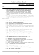

Keypad and Door Stations
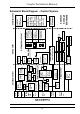
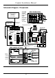
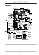
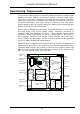
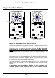
Figure 2.1 - Keypad and Door Station Settings
Open the Keypad housing by gently pushing a screwdriver into the two
slots at the front bottom one at a time while simultaneously prizing the
front cover from the base until the catch releases. Do Not insert the
screwdriver in too far or twist the front cover away from the
base as this will break the catches. Separate the front and back
housings by pulling the top housing firmly and squarely away at the
bottom edge.
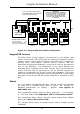
Mount the back housing on the wall using the screws supplied. Connect
the 6 wires from the terminal blocks on the Keypad to the Comfort PCB
according to the connection diagram above. The Comfort Panel should
be switched off during the Keypad installation.
The total resistance of each 12V and ground wire run should be less
than 5 ohms. If necessary, use an extra pair of wires for 12V and 0V
ground.
If more than one Keypad/Door Station is used, connect their
12V and ground wires directly back to the Comfort control
panel. Do not connect in series.
Comfort Installation Manual
29
Keypad
C B A
Key Tone
(Remove for soft)
JP6
SW4
Tamper
JP7 - TAMP
(Remove to enable)
SW1
ID Selectors
Microphone
Loudspeaker
Volume
Control
PC01-007C
1
2
3
JP5
KP
DP
Bk light
On Nor
JP4
Door Station
C B A
SW4
Tamper
JP7 - TAMP
(Remove to enable)
SW1
ID Selectors
Microphone
Loudspeaker
VR1A
Volume
Control
PC01-007C
JP5
1
2
3
KP
DP
JP8