
Installation manual
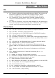
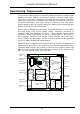
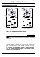

Jumper Settings and Adjustments
v SW1 - Reset Switch. This reset switch should be pressed after
downloading a configuration from CS-Xpress or after changing a
Location setting using Menu 7,4,1.
v J1 - (2 position header) - Leave Open
v J Z1 -JZ8 3x8 way header - Insert shunt in the position nearest the
terminals for the corresponding Zone 1 to 8 if no EOL resistor is used for
the zone. Insert a shunt in the position away from the terminal block if
Double EOL resistors: 2K7 connected in series and 4K7 is connected
across the contact.
v J10 (3 position header) - Shunt inserted over position 2 and 3 (normal
position). This jumper is used when programming a new vocabulary
using the Voice Programmer.
v J19 - 2 way header. Volume setting for Siren sounds on Keypads. Shunt
for louder.
v VR3 - Speaker Volume for advisory tones. Alarm tones (e.g. for
Intruder and Fire) are always at full volume regardless of this setting.
v VR1 - Keypad/Door Station Mic level adjustment
v VR2 - Do not adjust! - Telephone line length compensation-echo
cancellation
Location of Panel
Do not remove printed circuit boards from the cabinet as they are
‘statically sensitive’ and may be damaged with incorrect handling. Take
precautions against damage by static discharge by using an anti static
wrist strap tied to a suitable earth point. Remove the knockout holes,
protect with rubber grommets and mount the cabinet to the wall.
The system should be mounted in a dry area, with access to an
un-switched AC power source and incoming telephone line.
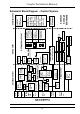
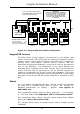
Panel Mounting
The control unit should be fitted at an early stage of the installation so
that runs can be connected in as they are completed, thus verifying
that the zone/cable/detector circuit is operational and the relevant
electrical testing and connections may be performed during daylight
hours. This can be done using the backup batteries even if no mains
power is available. Run large 40-60mm trunking across the top or
bottom of the panel with cut-outs allowing the cables to enter the
panel at any mublicon entry point. Screens should be tied back to the
earthing posts as they enter the panel. Mount the fused spur connection
box ideally to the top left of the panel, it should be possible to run
1mm flat twin & earth cable from the spur box and under the panel to
the mains cable entry near the transformer. The cable MUST be
Comfort Installation Manual
25