
Installation manual
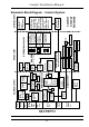
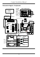
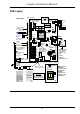
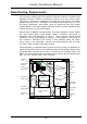
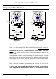
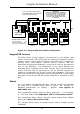

PCB Layout
12V Battery
(Sealed Lead-Acid)
Feeds control signals
onto 230VAC Ring
Main to switch
appliances and/or
lights.
U1
Program
U5
U4
24LC65A
(NVM)
Reset
VR3
U3
TR 0V
J9
Ringer
Power
LED
LEM
X-10
15 VAC
RJ11
X-10
POWERHOUSE
TW7223
X-10 Interface
Tel.
Out
Siren
Speaker/
Strobe
(Advisory Tones
not Voice)
Aux 12 V /
Det. Reset
Programmable
Detection
Circuits 1 - 8
RS485
Comms
Programmable
Outputs 1 - 5
(-ve applied)
6K8 - 100 ohm
IR LED
STEADY
FLASHING
RED GREEN
ARMED HOME
ALARM
TROUBLE
STATUS LEDS
+
Extension Sockets.
BT Line IN
Master Socket
Line OUT
A = 5
B = 2
C = 3 ringer
Master Socket
5
2
5
2 3
5
2
Tel.
In
MAIN CPU
+
OP 8
12v
OP 7
OP 6
12v
OP 5
OP 4
12v
OP 3
OP 2
12v
OP 1
SPK-
+ 12V
STR -
SRN -
SRN +
KB
KA
S12 V
COM
12V
Z8
COM
Z7
Z6
COM
Z5
Z4
COM
Z3
Z2
COM
Z1
JZ2
JZ3
3 2 1
JZ8
JZ4
JZ5
JZ6
JZ7
NOTE
A Master Socket MUST
be used on TEL-OUT to
ensure that all internal
phones will ring
U7
J11
Voice Prog.
3 2 1
J10
Siren 0v hold-off
and tamper return
VOICE
Volume (VR3) for
advisory tones and
sirens on, keypad and
Door Station spkrs.
12V / 0V Power lines to
be doubled to reduce
cable resistance.
REV 'E' PCB
REV E
Important
Each Keypad and Door
Station Cable MUST be run
separately from the panel.
VR1
JP1
CYTECH TECHNOLOGY
MIC
VR2
(Do not adjust)
Ringer module
should be
connected if the
doorbell and
reminder
messages are
required to ring
the phones.
RINGER
MODULE
MJ2
MJ1
MJ3
JP2
J4
J5
J8
SW1
JP10
JP9
JP8
JP15
Case Tamper
JZ1
Screen
connected
to earth at
CPU only
Data12V
V-Mic
V-MicData12V
J14
JP1
to J14
JP2
to J9
Keypad
Door Station
Intercoms
12V 0V KA KB
RS485
J15
Outputs Driver
PHONE
RELAYS
Comfort Installation Manual
24