
Installation manual

SECTION 2 INSTALLATION
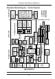
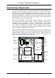
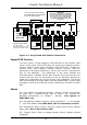
ICs
v U4 - System configuration Nonvolatile Memory (NVM). This is where all
Engineer programming information for a system setup is stored.
Part No: 24LC32A for 8 - 24 zone and 24LC65A for 32 - 64 zone
v U1 - Program IC. This IC contains the ‘firmware’ release for all of
Comfort’s embedded behaviour. This can be replaced for firmware
updates.
v U7 - Voice IC. Comfort’s voice menu and messages etc. are stored here.
It may be reprogrammed onboard for other vocabularies such as ‘Office’
using a Voice Programmer Board (VPM01) inserted into J11.
Connections
v MJ1 - TEL-IN. Connection to Public Switched Telephone Network..
v MJ2 - TEL-OUT. Connection to House phones.
v MJ3 - Connection to X10 /TW7223(Europe) ior TW523(US) Interface.
v JP1 - 15 VAC Transformer Input connection.
v JP2 12V Battery Connection for Sealed Lead-Acid Rechargeable Battery.
v JP3 - JP6, Zones 1-8 input connections. Circuits are DEOL, SEOL or Non
EOL.
v JP7 - 12V Auxiliary and Switched Supply (3 position terminal block).
v JP8 - RS485 KA/KB (2 position terminal block).
v JP9 - 12V Siren Connection for 12 Volt sirens, SRN terminal is the
trigger, SRN+ is 12V positive hold-off. 0V may be taken from GND at
J4.
v JP10 - Speaker and Strobe Connection for Speaker and 12V Strobe
Light.
v JP15 - RS485 Connection to PC and BUS interfaces (Pin 1 - 4 =
12V,0V,KA,KB).
v J2 - Header for Program Transfer Board connection
v J4 - Connection to Panel and Bell box Tamper Switch. Short terminal
block with wire-link if tamper Input is not used.
v J5 - LEM Connection Point for ribbon cable.
v J6 - Mains Power On LED header. (no resistor required, it is on the PCB)
v J11 - 9 way header for voice Programmer Board
v J13 - For Australian use only
v J9, J14 - Headers for connection to Ringer Board J1 and J2.
v J15 - 4 way header for RS485 Upload/Download and 12v supply.
v J23 - Test connector (4 way header)
Comfort Installation Manual
21