Comfort Installation Manual Section 1 General Information . . . . . . . . . . . . . . . . . . . . . . . . . . . . 8 Specifications . . . . . . . . . . . . . . . . . . . . . . . . . . . . . . . . . . . . . . . . . . . . . . 8 Ordering Information - Products and Accessories . . . . . . . . . 11 Year 2000 Compliance Statement . . . . . . . . . . . . . . . . . . . . . . . . 12 What do I read first? . . . . . . . . . . . . . . . . . . . . . . . . . . . . . . . . . . . . . . 12 Manuals for Installers . . . . . .
Comfort Installation Manual Using 12V Supplementary Supplies . . . . . . . . . . . . . . . . . . . . . . Connection to RedCARE or DualCom . . . . . . . . . . . . . . . . . . . . . . Reporting Comfort Line Fault . . . . . . . . . . . . . . . . . . . . . . . . . . . Remote Reset - RedCARE /DualCom . . . . . . . . . . . . . . . . . . . . . . Resettable Fuses (PTC) . . . . . . . . . . . . . . . . . . . . . . . . . . . . . . . . . . . X10 Connection (MJ3) . . . . . . . . . . . . . . . . . . . . . . . . . . . . .
Comfort Installation Manual Zone Types . . . . . . . . . . . . . . . . . . . . . . . . . . . . . . . . . . . . . . . . . . . . . . . 64 Table 8 - Zone Types - Security Mode Assignments ............. 65 Instant/Alert/Perimeter Zoning for False Alarm Filtering . . . . . . . . . . 65 Table 9 - Zone Types (Alarm Type Assignments) ............... 66 ................ 67 Selecting a Zone Type . . . . . . . . . . . . . . . . . . . . . . . . . . . . . . . . . . . . . .
Comfort Installation Manual Door Station Programming . . . . . . . . . . . . . . . . . . . . . . . . . . . . . . . . 84 Advanced Programming . . . . . . . . . . . . . . . . . . . . . . . . . . . . . . . . . . . 84 Preventing the two pulses on the siren when Away Armed . . . . . . . . 84 Changing the Siren duration for any Alarm 84 .................... Resetting Latched Detectors After Alarm (v4.101) .............. 85 Programming Entry door to cause an instant alarm (not delay) in Night Mode . . . .
Comfort Installation Manual Is the Siren Duration restarted during Alarm by new zone activations? . . . . . . . . . . . . . . . . . . . . . . . . . . . . . . . . . . . . . . . . . . . . . . 97 Section 6 Engineer Menu . . . . . . . . . . . . . . . . . . . . . . . . . . . . . . . . . 99 Zone(1) . . . . . . . . . . . . . . . . . . . . . . . . . . . . . . . . . . . . . . . . . . . . . . . . . . . 99 Zone Description (1,1) 99 10 ............................................ 0 10 Entry Path (1,3) ...............
Comfort Installation Manual 10 6 10 Description (3,1,1) ......................................... 7 10 Control Action Key (3,1,2) ................................... 7 10 Control Action Words (3,1,2,1) ............................... 7 10 Control Action Response (3,1,2,2) ............................. 8 11 Holiday Settings (3,2) ....................................... 0 11 Time Program (3,3) ......................................... 1 11 Day of Week (3,3,1) ........................................
Comfort Installation Manual 11 8 11 Monitoring Station Voice Station Option (4,1,4,4) ............... 8 11 Entry/Exit Time (4,2) ....................................... 9 11 Entry Time (4,2,0) ......................................... 9 11 Exit Time (4,2,1) ........................................... 9 12 Entry Warning Time (4,2,2) .................................. 0 12 Night Exit Time (4,2,3) ...................................... 0 12 Security Options (4,3) ......................................
Comfort Installation Manual 12 7 12 Dial Test (8,3) ............................................. 8 12 Siren Test (8,4) ............................................ 8 12 Strobe Test (8,5) ........................................... 8 Engineer Test Mode (8,6) - use for keypad and doorphone tampers 12 . 8 Engineer Menu Flowchart 12 ................................. 9 Technical Support 13 .......................................... 0 Security Check (8,2) ........................................
Comfort Installation Manual SECTION 1 GENERAL INFORMATION Specifications Zones w 8 fully programmable zones on Control Panel, expandable to 16 or 24 with Local Expansion Module (LEM) and 64 with Remote Expansion Module (SEP02) Each zone configurable for 0 or 2 end-of-line resistors w Up to 32 predefined Zone types to simplify zone configuration w Surge/Over voltage protection for each zone w Power Supply w 16.
Comfort Installation Manual Memory w w Non-volatile memory maintains configuration during total removal of power Event log with 250 events which can be accessed remotely or locally. Alarm Types w 32 programmable alarm types including user-definable alarm types w Predefined alarm types include Intruder, Fire, Panic, Duress, Arm , Disarm etc. Each alarm type selects a siren pattern, telephone combination, can trigger a user-defined response, which turns on/off appliances, lights etc..
Comfort Installation Manual w Tamper switch (24 hour) w Loss of Communications Trouble alarm w Back-lit keys w Dimensions: h=158 mm, w= 90 mm, d= 35 mm, weight 300g boxed Telephone Answering machine w Digital Answering machine with 10 minutes of recorded messages w 8 programmable mailboxes with individual sign-in codes. w Recorded messages with individual time/date stamps. w Answering machine is accessible from any phone in the house.
Comfort Installation Manual Emergency Menu w Quick activation of Fire and Panic using telephone or Keypad Test Features w Battery Test - Immediate or at programmed intervals w Security Check (walk test) zone activation is announced on Keypad w w Dial test - dials to all programmed telephone numbers, pagers, Central Stations, audible on Keypad Siren Test - Momentary activation w Strobe Test. - turns on and off the strobe.
Comfort Installation Manual w BT1270 - Battery 12V 7AH (Sealed Lead-Acid) w TB02 - 2 way Terminal Blocks w TB03 - 3 way Terminal Blocks w Model LEM01 - Local Expansion Module 8+8 (8 zones, 8 outputs) w EOL4.7K - 4.7K End-Of-Line insulated resistors w EOL2.7K - 2.
Comfort Installation Manual which are found after entering the Engineer Code and shows the Flowchart for overall view Keypad/ Door Station Installation Manual This leaflet show how to connect and install the Keypad and Door Stations to the Comfort control panel. The information is also found in this manual. Programming Worksheet The worksheets are the place where you write down your customer configuration and programming settings.
Comfort Installation Manual Manuals for Users Quick Start Guide This guides the user on how to operate Comfort using the Keypad and its function keys. very often this is the only thing the user needs to read. Users Reference Manual This is a detailed users guide for those who want to make full use of Comfort’s unique capabilities. Design Considerations and Applications Default Configuration and Responses The default settings (default.
Comfort Installation Manual Think future retrofit Comfort is one of the most expandable systems around! Installers can benefit from ongoing upgrades and modifications as there is so much ‘add-on potential’. Selling to an existing customer is always easier than finding new customers. A customer may wish to connect to a Central Station or add security lighting.
Comfort Installation Manual Radio Transceiver Module TM12U. These two devices can also be used to provide a wireless interface to perform any of Comfort's Responses. See 'X-10 received codes' in Table 32. Offices can be particularly bad for noisy mains supplies and in many instances will prevent X10 signalling from being viable. X-10 address can be categorised by their applications. You may need to switch OFF all of one particular address at once.
Comfort Installation Manual normally open side of each relay. Whichever relay operates will present it’s own image to be seen on the monitor. It is usually better to mount the relay board in a junction box with BNC panel mount socket connectors for 4 video IN and 1 video OUT such as our UNIBOX which allows four Relay Boards to be mounted together or 2 boards on top of the SEM02 zone expansion module.
Comfort Installation Manual contact for 1 second using action code 130 (Response 79 -Output 1), the gate will then close after a pre-set time determined by the gate controller. Photocells protect the gate from closing onto a car and also initiate an opening action when the beam is broken. By using another Comfort output with a normally closed contact in series with the photocell, the gate can be permanently held ‘ open’ once the pulsed ‘open’ command from the other relay has been sent.
Comfort Installation Manual SEP01 & SEP02 (17- 64 Zones, 17- 64 Outputs) The Slave Expansion Panel SEP02 consists of a small boxed unit (Unibox), with a 12V Slave Expansion Module consisting of 8 zones / 8-outputs and 1 Bell output. LEM boards model LEM01 can be piggy-backed over this SEM PCB using 25mm posts. (16-zone boards model LEM03, cannot be used with the SEP’s or for installations with more than 24 zones). It is connected to the main panel via three cores of the cable: KA, KB, and 0V.
Comfort Installation Manual SECTION 2 INSTALLATION ICs v U4 - System configuration Nonvolatile Memory (NVM). This is where all Engineer programming information for a system setup is stored. v U1 - Program IC. This IC contains the ‘firmware’ release for all of Comfort’s embedded behaviour. This can be replaced for firmware updates. v U7 - Voice IC. Comfort’s voice menu and messages etc. are stored here.
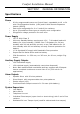
Comfort CPU 22 12-Volt OUTPUTS 1- 8 SYSTEM CLOCK ZONES 1- 8 MJ3 X-10 RS485 KA - KB DATALINE J14 TEL. OUT TEL. IN Relay Module (RLY01) 4 x 12V LEM (LEM01) 9 - 16 Zones 9 - 16 Outputs Door Stations 1-3 Homepilot.
Comfort Installation Manual Schematic Diagram - Peripherals REV 'E' PCB RELAY BOARD (RLY01) VOLT-FREE OUTPUTS Use to control: Curtains, Lights, Gates,CCTV, Lock-release, RedCARE and Paknet Transmitter RedCARE, DUALCOM or Paknet Transmitter 24-ZONE OPTION CYTECH TECHNOLOGY RELAY BOARD OP4 12v OP3 OP2 12V NC4 NO4 COM4 NC3 NO3 COM3 NC2 NO2 COM2 NC1 NO1 COM1 Outputs 9 - 16 (-ve applied) 16-ZONE LEM (LEM03) Inputs 16-24 instead of outputs OP1 4 x 12V Inputs 4 x NO/NC Contact Outputs RS232 PC Interfa
Comfort Installation Manual PCB Layout Outputs Driver REV 'E' PCB NOTE A Master Socket MUST be used on TEL-OUT to ensure that all internal phones will ring MAIN CPU REV E OP 8 12v U3 OP 7 OP 6 + RED STEADY OP 2 U1 SPK- STR SRN - JP10 JP8 Program JP9 SRN + RS485 Comms VR3 U5 KB RS485 COM COM 12V / 0V Power lines to be doubled to reduce cable resistance.
Comfort Installation Manual Jumper Settings and Adjustments v SW1 - Reset Switch. This reset switch should be pressed after downloading a configuration from CS-Xpress or after changing a Location setting using Menu 7,4,1. v J1 - (2 position header) - Leave Open v J Z1 -JZ8 3x8 way header - Insert shunt in the position nearest the terminals for the corresponding Zone 1 to 8 if no EOL resistor is used for the zone.
Comfort Installation Manual firmly anchored using the cable tie and adhesive pad provided next to the cable entry hole. Do not run mains cable through the same entry hole as low voltage circuit cables. Sharp metal entry holes should be protected with edge strip or rubber grommets. Always connect the earth from the mains cable to the panels mains earthing point terminal block, use earth sleeving to protect the exposed earth wire.
Comfort Installation Manual should be multiplied by the minimum time duration that is required under the relevant standards. The Amp/hour battery size should be of a higher capacity than the result of the calculation. It is always advisable to install the highest capacity battery which can physically fit into the enclosure (7A/hr). E.g.: QC = 0.650 A (650 mA) 8 hours required stand by QC x 8 = Battery Size A/hr (Min) 0.650 x 8 = 5.
Comfort Installation Manual Cable Routing / Requirements The minimum cable type to be used for detection devices, sounders and Keypad and Door Station connections should be 6-core alarm cable (7/0.2mm). This has a resistance of 8 ohms per 100 metres. Screened cables are preferred for Keypads, Door Stations and each one run from the panel separately. Use spare cores to double-up the 12V power supply cables to the each control station to reduce circuit resistance and further improve current performance.
Comfort Installation Manual Keypad and Door Stations Loudspeaker Loudspeaker Volume Control VR1A Volume Control SW4 Tamper C B A Bk light On Nor SW4 Tamper C B A SW1 ID Selectors SW1 ID Selectors JP4 1 2 3 1 2 3 Key Tone (Remove for soft) JP6 JP8 PC01-007C Keypad JP5 Microphone KP DP JP5 KP DP JP7 - TAMP (Remove to enable) JP7 - TAMP (Remove to enable) Microphone PC01-007C Door Station Figure 2.
Comfort Installation Manual IMPORTANT Ensure that each Keypad's 12V/COM wires are connected directly to the Control Panel and not in series. It is recommended that 8-core cable is used to double-up spare cores with 12V Aux supply feeds to reduce voltage drop. Screen connected to earth at CPU only. Zone 'COM' terminals are at 0V and may be for screen earth connection.
Comfort Installation Manual JP8: Disable Doorbell button. When shunt is removed, door station button is disabled. The shunt is removed when the Door Station is used as a keypad (JP5 to keypad position) for announcement. This applies to PC07-007C only. SW1: ID selection Setting the Microphone Levels On the Comfort CPU, VR1 sets the MIC recording and listening level for the Microphone.
Comfort Installation Manual Keypad / DoorStation ID Selection: Set the headers SW1 according to the ID of the Keypad according to the table ID SW1- C SW1 - B SW1 - A 1 2 3 4 5 6 7 8 Short Short Short Short Open Open Open Open Short Short Open Open Short Short Open Open Short Open Short Open Short Open Short Open If a Door Station is installed, then a maximum of 3 Keypads may be installed using the Comfort PSU. The ringer module RGR02 may also be fitted.
Comfort Installation Manual Speaker and Strobe (JP10) Connect a strobe light to the 12VF and STR - outputs if needed. Observe the polarity. For UL Installations use a UL approved strobe, eg Wheelock LS1-12-VFR. In the event of an alarm, the strobe is turned on until the system is disarmed. The Strobe and speaker terminals have a combined current limit of 1 A, protected by a resettable fuse (F3) Connect an 8 ohm 5W (minimum) speaker to the SPK- and 12VF outputs. Polarity is not important for a speaker.
Comfort Installation Manual Panel Tamper Switch - (N.C.) Remove Link to enable panel casetamper 0V Hold Off Tamper Return. 12V + Hold Off SRN Trig - ve Strobe - ve Strobe +ve 0V - TR SRN+ SRNSTR12VF SPK- 1K-Ohm Pull-Up Resistor may be needed if siren rings permanently Comfort Main PCB External Siren/ Bell Figure 2.
Comfort Installation Manual Telephone Connections Single Line Telephone Connection Comfort must be connected in series between the incoming telephone line and the house phones using solid core telecom cable and not stranded alarm cable. Use the proper jointing IDC (Krone) tool for making connections rather than a screwdriver. Connect the incoming telephone line to the TEL IN Terminal Block. Connect the telephone wires going to the house phone(s) to the TEL OUT Terminal Block.
Comfort Installation Manual Comfort CPU MJ1 BT Line IN 2 TEL IN 2 5 5 make joint Master Socket NT5 A=5 B=2 C = 3 ringer 3 House Extensions 4 REN recommended Maximum by Telephone companies. 3 5 TEL OUT MJ2 2 3 5 2 3 5 2 Master or secondary socket. see below Secondary Sockets With Ringer Module Without Ringer Module Use a master socket on Tel Out if the ringer module is used for doorbell and reminder messages. The master socket creates a ring connection (3) from the line (2,5).
Comfort Installation Manual UK - ISDN Digital Phone Systems (ISDN 2e) Comfort can connect to Digital Phones systems, but only onto an analogue extension or terminal adaptor. The ringer module is not required for such installations as the system doorphone operation has to be set-up to initiate a dial-out in all modes. This is achieved using responses. Full details are provided in the Applications Manual or on the Technical Website www.comfort.org.uk/technical/indexapp.html.
Comfort Installation Manual normal extension phone. In this case, the system should be connected to an extension which is designated to be connected to one of the exchange lines in the event of a power failure. If the system is connected as an extension of a PABX and it is required to dial a number to obtain an outside line, program the PABX Option in the Engineer Menu (7,2), and the PABX Key (7,2,1) to the prefix to be dialled to get an outside line (usually 9 or 0).
Comfort Installation Manual To provide a ‘global tamper’ protection for these types of zone configurations, assign one zone as a ‘tamper’ zone type 20 and connect all zone wiring tampers in series to this tamper zone. Zones must be normally closed. JZ1-8 3 2 1 Zone Alarm COM Alarm Zone Shunt on pins 1 & 2. (Near to terminals) Tamper Tamper Figure 2.
Comfort Installation Manual The 2 EOL resistors should be connected at the contact and not at the control panel. With 2 EOL resistors connected in this way, the system is able to distinguish open and closed contacts from open circuit and short circuit wiring providing full supervision of the zone contacts and cables. Any short or open circuit fault will trigger a Zone Trouble Alarm which can be reported to the programmed phone numbers.
Comfort Installation Manual RLY01 OP8 12V OP7 Output OP6 Terminals 12V OP5 RELAY 'PULSE' WILL RESET SHOCK AND SMOKE DETECTORS USING ARMING RESPONSE IN LOC 1850 Detector 3 Detector 2 Detector 1 + + + PWR PWR - 4K7 CCT PWR - 4K7 CCT LNK 2K7 TAMP - 4K7 CCT LNK TAMP Zone Input Terminals TAMP Single cable returns to the panel zone 4K7 = Yellow, Violet, Red 2K7 = Red, S12V Violet, Red 0V 12V Double JZ8 EOL Z8 COM 3 2 1 Position JZ7 Z7 3 2 1 Comfort Main CPU May need to use a terminal b
Comfort Installation Manual 2K7 EOL resistor required for UL installations J4 Tamper International Versions COM Tamper Tamper Remove Link to enable panel case- tamper 0V - TR J4 Tamper Return. CPU Tamper Switch - (N.C.) 0V European Versions Figure 2.12 Tamper Input connection ‘Negative Applied’ Detectors Certain types of detector such as outside PIR’s and photocells provide an open-collector output as a trigger rather than a relay output.
Comfort Installation Manual NOT to the wire that returns to the zone COM terminal, which is already at 0V . ‘GJD XL or Opal’ detectors have both -ve alarm trigger outputs and a built-in photocell -ve output. Comfort ‘default ’ uses zone 13 for a light sensor. Output Terminals OP1 - OP8 (JP11-JP14) Each of the 8 outputs may be connected to infrared LEDs, indicator LEDs or external relays.
Comfort Installation Manual High Voltage Box OP L COM 2 way manual switch 12V N/C OP N N/O Lighting Relay (10A) Light Fuse N/O IN N/C COM IN N COM Feedback Relay Figure 2.14 - Output Control with Feedback Instead of an AC operated relay for feedback status indication, a current sensor (Model CSM01) can be used, as shown in the next diagram. The insulated “Live” mains wire goes through the loop of the current sensor. Do not put both L and N wires through the sensor.
Comfort Installation Manual Connection to Visible or Infrared LEDs Connect infra-red LEDs to the outputs according to the figure below. A series resistor of 100 ohms 2 Watt should be connected between the infrared LED and the output. 100 ohm 2 W for IR led - Output 12V Output + + Infrared LEDs Use 2 or more for greater range Figure 2.16 - Output Connection to Infrared LED For Infrared LEDs, the value of this resistor depends on the distance from the LED to the appliance and the incident angle .
Comfort Installation Manual 12V Auxiliary Supply Outputs (12V and S12V) 12V and GND supply 12V to devices which require power e.g. movement detectors. The S12V terminal provides 12V to external devices which require resetting when activated, e.g. smoke detectors. The S12V supply is switched off for 5 seconds whenever the system is disarmed. Total continuous current from these and the Output 12V terminals should not exceed 1 Amp. These terminals are current limited by resettable fuses.
Comfort Installation Manual Using 12V Supplementary Supplies Larger installations that place additional current demands will require the installation of one or more supplementary power supplies. As a guide, if the normal standby (quiescent) current of the system is greater than 850mA, then an additional 12V DC power supply should be installed. Ensure that the 0V ground of Comfort Main Auxiliary is connected to the 0V of all supplementary 12V Power supplies. +12V should NOT be commoned.
Comfort Installation Manual Connection to RedCARE or DualCom Some installations may require ‘Line Fault Reporting’ such that the Central Station is informed when a ‘line cut’ has occurred using means other than the telephone line that has been cut. A stand-alone RedCARE STU or DualCom Paknet interface card may be installed to the system to transfer alarm status and line fault information to a central station using a radio method or ‘loss of carrier’ method.
Comfort Installation Manual Alarm is produced, this can be treated as an ALARM CONFIRMATION signal or SECOND ALARM. e.g. To transmit A CONFIRMED ALARM signal using REDCARE or DualCom set up the alert alarm type and response to trigger an output and connect it to trigger a Channel 3 (intruder) on the STU and the intruder Alarm type can be used to trigger a Channel 7 (Confirmed Alarm). Please refer to above italics for notes on restoring these outputs on disarm.
Comfort Installation Manual To provide ‘Local Audible’ Line Fault monitoring the RedCARE STU MUST use the same telephone line as Comfort panel and should be connected to the incoming line and NOT the outgoing line otherwise you may suffer Line Faults on the RedCARE. DualCom Connections DualCom is connected slightly differently. For ‘Local Audible Line Fault’ monitoring, the telephone line MUST NOT share with the Comfort line in any way, rather it must have it’s own telephone line connection.
Comfort Installation Manual This is measured by placing a digital meter set to current range of 2 Amps or more in series with the ‘Red’ back-up battery lead using insulated crocodile clips. Now, remove the mains supply to the panel for a few seconds and note the meter reading. if it is 850mA or above then an additional power supply should be fitted. Resettable Fuses (PTC) The auxiliary and battery supplies are protected by two positive temperature coefficient resettable fuses of 1A and 2.5A respectively.
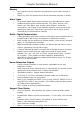
Comfort Installation Manual X10 Connection (MJ3) X-10 Socket MJ3 14" RJ11 TW7223 OR TW523 Comfort Panel TW7223 Interface lead showing correct RJ11 plug orientation using flat 4-core telecom cable X-10 Interface X-10POWERHOUSE RING MAIN WIRING X-10 POWERHOUSE LW10 AW10 X-10 POWERHOUSE APPLIANCE MODULE O M K A 15 C 1 LAMP MODULE 3 E 13 I G HOUSE 5 15 11 9 7 UNIT 1 L 1 2 Switch Module 3 5 13 11 O M K A 15 1 3 C E 13 I G HOUSE 5 11 9 7 UNIT 9 7 O M AM12 Lights Dishwashers
Comfort Installation Manual module (LD11) as well as the Wall Switch (LW10) which may also be used in a Comfort system setup. Mains Supply It is always advisable to check a property for the ability to transmit X-10 signals reliably around the electrical ring-main using the UR24/TM12U before specifying the use of X-10. Some buildings with noisy mains supplies or appliances can produce a masking effect to X-10 signals, also X-10 signals can attenuate over distance.
Comfort Installation Manual the main zones on the panel. if using CS-Xpress this location is not set automatically. The 12V outputs, however, should only be used to drive up to a 100mA load. Each output may also be used for infrared signalling.
Comfort Installation Manual Power-On Checklist 1 2 3 4 5 6 7 8 9 10 11 12 Check that Keypads and Door Station wiring are connected, the ID jumpers for each Keypad and Door Station are set correctly. At least 1 Keypad should be connected for easy programming Measure and log the functional resistance of each detection circuit Terminate all zone wiring into the respective Zone Terminal Blocks on the Main board or Local Expansion Module (LEM) and label accordingly.
Comfort Installation Manual SECTION 3 PROGRAMMING Comfort Security System Zone Zone Type (0-31) Description (4 words) Away, Night, Day Home Mode Settings Trouble Alarm Type (0-31) Entry Path ON Response Normally open/ closed? Entry Door? OFF Response Sensitivity (0-7) 24 Hr? Alarm Type (0-31) Siren Type (0-19) Strobe? Siren Delay? Dial Delay? Phone No 1 On/Off Phone No 2 On/Off Alarm State (Idle, Trouble, Alert, Alarm) Dial Out? CMS Report Code Dial Indexes Phone No 3 On/Off Phone
Comfort Installation Manual actions taken by the system during alarm activation, like whether it dials out, and if so to which numbers, whether the siren and strobe is turned on etc. The Siren Type determines the pattern and duration of the sound. This highly configurable system allows great flexibility in programming a system, but it also simplifies programming because of default settings. Programming consists of assigning words and Zone Types to each zone.
Comfort Installation Manual selected and the time matches the programmed time (to the minute). When this happens, the programmed Response is activated. For example, in an office, Time Program 1 may be programmed for 9:00 am on Monday, Tuesday, Wednesday, Thursday, Friday to activate a Response which disarms the security system and turns on the lights, air-conditioning and photocopying machine.
Comfort Installation Manual Strobe Arming ‘Flash’ (Macro Response 28) The system default setting uses the Away Mode as a means of triggering the strobe light for 3 seconds (Response 118 within Away Macro response 28) to signify successful arming. Siren Arming ‘Pulse’ The system default setting ‘Siren Type 5, Table 25,Away Armed) will also will produce two siren pulses upon successful arming of the system to Away Modes.
Comfort Installation Manual CS-Xpress PC Software / UCM01 Interface Installation Windows 95/98/2k Installation Comfort CPU 1 - Insert CD ROM into Drive A screen with icons will appear. RS232 2 - Click on Setup, click next, next, RS485 when prompted. 3 - Then check the tickbox: + JP2 P1 U6 J2 Yes, Launch the program file, then ok. + JP2A U5 UCM4 D9 D10 within COPY U2 SW6 U1 SW3 UCM 4.XX SW7 UCM3 KB KA COM 12V SW1 D12 D11 CS-Xpress 3 is installed ‘Program Files’ folder.
Comfort Installation Manual Troubleshooting CS-Xpress Symptom Possible Cause LED’s D9 and D10 are not flashing No power to the UCM or Location 1672 set to '0'. ‘Timed Out Waiting for Reply’ This can indicate that the comms port on the PC is set incorrectly or the RS232 cable is not connected or the wrong type. Too Many Checksum Errors old version This could be caused by an incorrect upgrade routine from an older version of CSXpress. De-install the and do a fresh install.
Comfort Installation Manual When the reset is required, Comfort automatically enables Engineer access so that the Engineer may sign-in without the user needing to authorise the access. Additionally, the engineer may be called by the system if the user presses the function ‘0’ command and Alarm Type 30 has been programmed by the Engineer with Telephone number 8 prior.
Comfort Installation Manual Program and Engineer Menus There are 2 levels of programming access, 1 2 Program Menu - allows a master user to change settings pertaining to the answering machine, home automation and certain security features. Program Menu is accessible from the user Master Code (User Menu 9) as well as Engineer Menu 9. This is described in detail in the Program Menu Reference (User Reference Manual) Engineer Menu - Allows change in security, zone, home automation and alarm settings.
Comfort Installation Manual When the correct code has been entered, the system enters the Engineer Menu. To Select a sub-menu or option from the voice menu, enter a number on the telephone keypad as instructed (digits 0-9,*,#). It is not necessary to wait until the voice menu is completed before entering the digit to select a sub-menu or option.
Comfort Installation Manual Using the Program Worksheet In this section, we will work through the Worksheet, and show how to program each item. Keep a copy of the program Worksheet handy. The system is programmed either via Engineer Menu, or by Locations. To Enter Engineer Menu, enter the Engineer Code (default *6789#). The Notation X,Y,... used in this section indicates the Menu path, i.e. what keys to press to get to the required sub-menu.
Comfort Installation Manual Table 2 - Status Indicator Output Assignments This table gives the Locations in outputs (1 to 16) can be assigned to indicate the system conditions, shown. Enter the Output number in the locations given. For example, to indicate Phone Line Cut on output 4, Program Location 1695 with 4. Table 3 - Away Arming Method (Location 1692) Comfort has 3 methods of arming to Away Mode, i.e. when no one is in the premises.
Comfort Installation Manual after changing Zone Types, by pressing the reset button on the Comfort PCB. Press the Reset button after all changes are completed, rather than after each change. Characteristic Value Remarks Instant, Alert, Perimeter, Inactive Each zone type has a setting in each mode: Off, Night, Day and Away. This gives flexibility in defining the behaviour of the zone types. For example, a Zone Type may be Inactive in Off or Day Modes, Alert in Night Mode and Instant in Away Mode.
Comfort Installation Manual type can be assigned to any one of these filter settings for each security mode (Security Off, Night, and Away/Holiday). The use of Alert and Perimeter Zones is a useful tool in preventing false alarms, but requires careful planning and design on the part of the installer. Refer to the table below for the flowchart which explains the sequence of zone activation to trigger an alarm.
Comfort Installation Manual Table 10 - Zone Types - Miscellaneous Settings An Entry door zone type starts an entry delay if the door is open when the system is armed. In the Final Door arming method, it also terminates the exit time when it is closed during arming to Away mode. Each Zone Type can be defined as Normally open or closed. Most security sensors are Normally closed. Normally Open and Closed contacts cannot share the same zone. The sensitivity of the zone (i.e.
Comfort Installation Manual 4 - Alert Away (NC, Alert) This circuit is the same as zone type 3 except it is not active during Night and Day Mode . 5 - Instant Night/Away (NC, Intruder Alarm) A circuit that will generate a full alarm during Night and Away Modes and not Day Mode.
Comfort Installation Manual 12 - Panic Audible (N.C, Panic Alarm) (N.C, 24-Hr circuit) A 24-Hr circuit that will generate a full audible alarm condition when activated. Can be bypassed, but bypass can be disabled by setting 24 Hr ON in Table 10. Panic Silent (Siren Type 0 in Alarm Type 9) To select a silent Panic alarm type that will just remotely signal to the Central Monitoring Station and other phone numbers, change the siren type in alarm type 9 to ‘0’ (no siren sound). This is found in Eng Menu 2,9,5.
Comfort Installation Manual 20 - 24-Hr Tamper (N.C, Tamper Alarm) A circuit that will generate a full tamper during all modes. System cannot be armed when this zone type is active. Can be bypassed by default, but bypass can be disabled by setting 24 Hr ON in Table 10 21 - Doorbell (N.O, Door Station) The doorbell of an independent intercom system can be linked to the Door Station by providing a normally open contact to a zone of this type.
Comfort Installation Manual 29 - Instant Day /Away (N.C. Intruder Alarm) Similar to Zone Type 22, except that it is inactive in Night Mode. 30 - Instant Night/Away (N.O. Intruder Alarm) Similar to Zone Type 5, except that it is normally open. It is intended for PIRs in interior zones. 31 Instant Perimeter Away (N.O.
Comfort Installation Manual Circuits with this On response will cause a short two-tone ‘chime’ sound at the Keypads and speakers . This may be disabled by the user in Alert Menu 6 in Home Control. (Siren Type 20) 85 Cancel Entry in Night Mode Circuits with this On response will perform an immediate alarm if activated during Night Mode and respond as normal when in Away Mode. 86 Double Knock - Ext.
Comfort Installation Manual To prevent the system from being re-armed after a Soak Test zone failure, enter a Response containing action code ‘20’ into the Soak Test alarm type to cause an Engineer Reset lock-out. Table 12 - Phone Settings (Engineer Menu 4,1) Up to 8 phone numbers may be assigned for dialout during alarms. The phone numbers may be assigned as Monitoring Station (1st 2 numbers only), Voice Phone (landline or cellular phone), numeric pager or Alarm Voice Message.
Comfort Installation Manual the expiry of Exit time, if the system is not armed. It gives an Arm Fail Alarm, which is a local warning on the speaker and siren consisting of a series of short beeps. For the Final Door Arm Option (Location 1692=0), the exit time is terminated and the system is armed when the Entry Door is closed. For Arm after Exit delay option (Location 1692=1), the system is armed after the Exit time is all protected zones are closed.
Comfort Installation Manual Types. If the Alarm Type for a General Alarm is set to 0 (Nul Alarm), there will be no alarm activated. For example, if the general Alarm Line Cut is set to Alarm Type 0 by setting Location 7 to 0, the Security off/Trouble led will not flash and there will be no trouble beeping sound from the speaker and Keypad when the phone line is cut.
Comfort Installation Manual Item Value Menu Remarks Event Log Yes/No 2,6 Determines if this alarm type is reported in the Event Log Trouble Arm Yes/No 2,7 If the alarm type is Trouble state, whether the system may be armed when the alarm type is still active. Setting this to off will prevent the user from arming the system during this alarm. This applies only for Trouble Alarms and has no effect for alarms of other states.
Comfort Installation Manual Table 24 - Siren Duration The duration for each Siren Type is programmed in 2 consecutive Locations given in Table 24. The values to program in the two locations are given in table 24 for a range of durations. Table 25 - Siren Type (Output Settings) Each Siren Type can be programmed to output to the Siren (12V), Keypad or Door Station. It is always output to the Speaker (SPK+/-), but if the HI SPK setting is on, it will be at full volume, not adjustable by the VR3 trimmer.
Comfort Installation Manual No Action if the Action key has not been programmed. Enter up to 3 words from the wordlist (Table 40). If less than 3 words are entered, enter 255# as terminator. "ON" is 230#. Enter 255# for terminator. The menu announces the Actions words ("ON"), and asks for the Response Control Response 0 Enter Response and # key Enter the appropriate Response number from Table 33, which performs the desired function.
Comfort Installation Manual For version 4.107 and above, the control key feedback includes Output states, Analog Input values and Counter Values in addition to Input states. Feedback Value 0 1-64 65-128 129-191 192-255 Announcement None Input State (On/Off) Analog Input Value Output State (On/Off) Counter Value Range Input 1 to 64 Input 1 to 64 Output 1 to 63 Counter 0 to 63 To announce an Input state, just enter the Input number in the feedback location for the control key.
Comfort Installation Manual There are 16 Time Programs which can perform regular functions automatically at pre-programmed times. Each Time Program consists of an activation time, which day/s of the week for the activation, and a custom Response. A Time Program can be specified to run regularly for any combination of days of the week (Monday to Sunday) or just to occur during a specified Holiday and whenever Holiday Mode is set.
Comfort Installation Manual example, when armed to Away, all the lights and appliances may be turned off, or when disarmed, the heater can be turned on. To do this, enter a Response number for each of the Security Mode Responses in Engineer Menu 3,5. Arming to Holiday Mode activates the Away Mode Response.
Comfort Installation Manual Table 34 - Other Location Changes This table gives a list of Locations, some of which may not be mentioned in the other tables. Take note of the following Locations in particular: v 720 = Battery Test Interval . The interval in hours between automatic Battery Tests when the Battery Test Option (Eng Menu 8,1) is ON v 721 = Battery Test Duration.
Comfort Installation Manual Table 38 - User Authorisation Settings Each of the 16 User Codes may be assigned authorisation for Local Disarm, Local Arm, Remote Disarm, Remote Arm, Disarm on Alarm only, Security Menu (User Menu 3) Access, Home Control Menu (User Menu 4) Access, and Program Authorisation. These User authorisations settings can also be programmed in the CS-Xpress software.
Comfort Installation Manual Action 93 - Baby Monitor Mode Usage: 93, id, 91,25 Puts selected Keypad id in monitor mode, ie with its microphone on. Any other Keypad can listen to the selected Keypad, when the Function Key is pressed. 91,25 causes the system to go to the Baby Monitor mode Action 94 - Keypad to Zone Linkage Usage: 94, id When assigned to a zone response, it links the selected Keypad to the zone.
Comfort Installation Manual This section describes advanced programming tricks and tips. Preventing the two pulses on the siren when Away Armed By default, the external siren output gives two pulses when the security system is armed to Away (or Vacation) to provide confirmation of the armed state. In some installations, this may be undesirable.
Comfort Installation Manual beep tone which is heard on the minute. Check the time again at the same time the next day or several days later. Calculate the time error for one day by dividing the total time error by the number of days since the time setting. Program a positive or negative correction into the Location as described above. This can make Comfort accurate to within ½ second per day, or 15 seconds per month.
Comfort Installation Manual Programming a Bell Delay In commercial premises, it may be required to delay the Siren for a programmed time when an alarm is triggered. To do this go to Engineer menu, 2 for Alarm Type Menu, 5 for Siren Type. Press # to leave Siren Type unchanged. The menu goes on to Siren Delay, 1 for on, 0 for off. If a Phone Line cut is detected before or during a Bell Delay, the Siren is activated immediately.
Comfort Installation Manual main system. The zones which are omitted can be programmed as immediate in all modes to simulate an independent partition. Reporting Bypassed Zones Bypassed zones may be reported to the programmed phone numbers. Alarm Type 16 is the Bypass Zone alarm. Set the dialout to ON and program the combination of dial indexes 1 to 8 to report for this event.
Comfort Installation Manual The underlying rule is to advance at the beginning of the summer (March) and retard at the end (Oct). Important.
Comfort Installation Manual SECTION 4 TESTING AND COMMISSIONING The installation and programming should have been completed at this stage. 1 2 3 4 5 6 7 8 9 10 Go into the Test Menu (Engineer Menu 8 or User Menu 3,4) or Keypad F+3. Activate the Security Check menu and do a walk test. Activate every detector and ensure that the zone is announced on the Keypad. Detectors will not cause alarms during this test. Press any key on the Keypad to end this test mode.
Comfort Installation Manual 11 12 13 14 15 16 17 18 19 Use the local phone to sign in by pressing * code #. Each key pressed should be followed by a short beep tone to indicate that is has been recognised The voice menu should be heard, and the DTMF keys should be able to select the various menus. Program and Record the following messages using the telephone: - Greeting Message - Prog. Menu 1,3 (This may also be played on the doorphone, where required, involve the customer) - Alarm Message - Prog.
Comfort Installation Manual SECTION 5 TROUBLESHOOTING Troubleshooting Kit When installing Comfort or attending to problems on site, it is advisable to have the following tools in the tool kit: 1 2 3 4 5 Multimeter for checking continuity and resistance. A hands free telephone for checking telephone voice menu operation 12V Test lamps for checking outputs Default programmed U4 Non-volatile Memory (NVM) chips, in case certain settings have been corrupted or wrongly programmed.
Comfort Installation Manual Keypad/ Door Station Problems “Communications Failure” Home LED blinks and “Communication Failure, ID “ followed by the ID number is reported upon user sign-in. This means that a Keypad or Door Station or SEP02 is not communicating with the Comfort panel. The ID address of the unit which is not communicating is reported.
Comfort Installation Manual 4 5 Check that the MIC and Voice are connected to JP15 on the Control Panel. If voice is not heard, the problem is in the Audio path. Check that the Keypad Volume Control knob on the Keypad and the trimmer in the Door Station is not all the way down. None of the Indicator LEDs on the Keypad are on At least one LED should always be on steady or blinking.
Comfort Installation Manual Phone Problems Cannot Sign in on Local Phone When * is pressed on the local phone within 5 seconds (see 5 for adjustment of this time) of lifting the handset, there should be a relay click on the panel. Subsequent keys should have beep tones as acknowledgment that the system has detected the key presses. 1 2 3 4 5 If no relay click is heard, it could mean that the Keypad is being used.
Comfort Installation Manual volume for the trouble beep can be adjusted using the trimmer next to the speaker terminals. During an alarm, the speaker volume is at the maximum and not affected by the trimmer adjustment. (See section on Parallel Phones below) Parallel Phones There should be no telephones or faxes connected in parallel to the incoming line to the panel, otherwise when the parallel line is used, Comfort will detect a Phone Trouble.
Comfort Installation Manual Cannot dial out successfully 1 2 3 4 5 Check that the relevant Alarm Types have the Dial Settings on (Eng Menu 2,1) and the dial settings are enabled for the phones which are to be dialled ( 1 to 8) Does the telephone line have Call forwarding or Voice Answering (provided by the phone company)? This may prevent a dialout because Comfort may not detect a dial tone. See "Special Telecom Services” Do a Dial Test (User menu 3,4,3 or Engineer menu 8,3).
Comfort Installation Manual pressing 1 for next event, 2 for previous event, 0 for 1st event, 9 for last event, 3 for Next Day, 4 for Previous Day. See Engineer Menu 5,1 for a full description of the events which are recorded. False Alarm on Disarming This may be caused by connecting PIRs or Keypads to the S12V output instead of the 12V terminals. S12V and 12V share the same terminal block.
Comfort Installation Manual Does the system remain armed after removal of power? After a complete loss of power, including battery discharge, the system remembers its last state and restores it. If the system was armed to Away, Night or Day mode, it will re-arm to that mode when powered up again. The Date and Time will be reset to default after a complete power loss, and will need to be reprogrammed.
Comfort Installation Manual SECTION 6 ENGINEER MENU Engineer Menu Press 1 for Zone 2 for Alarm 3 for Control 4 for Security 5 for Event Log 6 to Change Sign-in code 7 for System 8 for Test 9 for Program Menu (Entering Eng Code will perform Engineer Reset - UK Only) Press # to End Zone(1) Enter Zone Number and # key Each zone can be programmed for Description (words), Zone Type, Entry Path, Zone On Response, Zone Off Response. System says the current settings for the zone selected.
Comfort Installation Manual Press 1 for Description : The currently programmed description is announced, followed by "enter new number and # key". Enter each word followed by the # key. Refer to the Word List (Program Table 1) for assigned word numbers. A maximum of 4 numbers may be programmed. If there are less than 4 numbers, enter 255 # to terminate. The description is used in zone announcements event log, alarm history, alarm tracking.
Comfort Installation Manual Zone ON definition depends on the Normally Open/Normally Closed setting of the Zone Type, i.e. Closed contact for N.O zones and open contacts for N.C zones. ( The Zone Response is activated even if the zone is Inactive (e.g. in Security Off), and before any Alarm Response triggered by the zone. Zone Off Response (1,6) System says the current OFF response when this zone is deactivated and asks for a new response number and # key.
Comfort Installation Manual Alarm (2) Enter Alarm Type and # key (0-31) Up to 32 Alarm Types can be selected. (See Alarm Types in Table 4). This menu allows the Dial settings, Alarm Response, Siren Types, Communicator Report Codes and other settings for the selected Alarm type to be changed. (Alarm Name) Press 1 for Dial Settings 2 for Response 3 for Description 4 for Strobe 5 for Siren Type 7 for Trouble Arm Option 8 for Alarm State Dial Settings (2,1) Dial Settings On (Off) Press 1 for on, 0 for off.
Comfort Installation Manual Enter Dial setting 1 to 8 Enter 1 to 8 to select a Phone Index. The current setting (1 or 0) may be changed by pressing 1 for ON or 0 for OFF to turn on or off the setting for the phone index. If the setting for the phone index in ON, activation of the selected alarm type will trigger a dialout to the phone index. This menu assigns dial settings to the Alarm Type.
Comfort Installation Manual number or the user number, depending on the alarm type, as the second digit. For DTMF Communicator formats e.g. Surgard and Contact ID, refer to the Communicator formats table in Worksheet Table 14 ( If this alarm is not to be reported, enter 15 in both digits, i.e. 15#,15#, corresponding to FF.
Comfort Installation Manual This refers to the Contact ID Class Code, which is a single digit number from 0 to 9. This is sent with the Contact ID report to Central Monitoring Station. It is ignored for other Central Station formats. Alarm Response (2,2) Response (0 to 99), Enter Response number and # key An Alarm Response or program may be performed when the alarm is activated.
Comfort Installation Manual If Siren Delay is on for an Alarm Type, the Siren will be activated only after the Siren Delay. The Siren Delay setting in minutes (0 to 255) is in the Siren Delay location 51. The value entered for Siren delay has an variance of -1 minute, i.e. entering a value of 2 minutes means the siren delay is actually 1 to 2 minutes. If the Siren Delay is OFF for an Alarm Type, the siren will be activated immediately without any delay.
Comfort Installation Manual The second level or Actions Keys selects the action to be performed once the Control Key is selected, for example “Press 0 for OFF, 1 for ON, 2 for Low, 3 for High”. The Control Menu is as follows: Enter Control Key Enter control key 0 to 9. This selects the digit on the telephone keypad for Home control. These control settings program the assignment of digits on the telephone keypad with the descriptions e.g. Digit 1 for "Living Room Lights", the control action description (e.g.
Comfort Installation Manual Enter the new word number and # key. Enter the next word in the same way. A Maximum of 3 words is allowed. If there are less than 3 words, enter 255 as the terminator. Control Action Response (3,1,2,2) Response 12 - enter Response number and # key Enter new response number 1 to 99#, or just # to leave response unchanged. Enter 0 if no response is required. From the Engineer menu, press 3 - Control Settings, 1 - Output Settings.
Comfort Installation Manual Press 1 for Description, 2 for Action Key Press 1 for Description. Up to 4 words can be entered from the wordlist (Table 1), as in the Zone Descriptions. The currently programmed words are announced, followed by Enter Word Number and # key Enter each word (0 to 254) followed by the # key. If there are less than 4 words, enter 255# as the terminator. The voice menu repeats the words entered. In the example enter words 6# (bedroom), 34# (light) , 255# (terminator).
Comfort Installation Manual Key Description Action Key Action Words 0 to 9 Description 1 0-255 0-255 0-255 0-127 Word 1 Word 2 Word 3 Word 4 0 OFF 229 255 34 Turn off X10 A1 0-255 0-255 0-255 0-255 1 ON 230 255 33 Turn on X10 A1 6 33 255 2 - 255 0 Not Used 3 - 255 0 Not Used 4 - 255 0 Not Used 5 - 255 0 Not Used 6 - 255 0 Not Used 7 - 255 0 Not Used 8 - 255 0 Not Used 9 - 255 0 Not Used Bedroom Lights 2 Resp Notes * - 255 0 Not Used
Comfort Installation Manual Enter the new month (1 to 12) and # key, or just # to leave the month unchanged. The voice menu will say the new month e.g. March Change Day, 1, enter new number and # key Enter the new day (1 to 31) and # key, or just # to leave the day unchanged. The system will not allow the entry of an invalid day e.g. April 31 or Feb. 29 for non-leap years. Holidays are used in Time Programs and Reminder Messages as part of the Day-of-Week settings.
Comfort Installation Manual Press 1 to select the day of week to be on, and 0 to select the day to be off. This determines whether the selected Time Program will be activated on that day of week. The same procedure is repeated for each day of week Use of Holiday in Time Programs If a Time Program Day of week is ON for Holidays, it will be active on any of the defined Holidays.
Comfort Installation Manual Enter Vacation program number and # key Enter the vacation program number (1 to 8) and # key The voice menu says the current settings of the selected Holiday program (e.g.) 6:00 am, 2 hours, ON response 3, OFF response 17 Press 1 for Start Time, 2 for Hours, 3 for ON Response, 4 for OFF Response Holiday Program - Start Time (3,4,1) e.g. 6:00 am, enter new number and # key Enter new Time (hours only) in 24 hours format, e.g. 12 for 12 PM, or # to leave the time unchanged.
Comfort Installation Manual e.g. Off Response 23, enter new number and # key Enter new OFF response number and #, or just # to leave the value unchanged. Enter 0# if no response is required This response is executed after the duration specified above has expired. Security Mode Response (3,5) A response may be specified to execute when changing to one of the Security Modes (home, away, night, vacation). For example, when arming to Away mode, all lights and appliances may be programmed to turn off.
Comfort Installation Manual The voice menu says the values of the bytes making up the Response, e.g. for Response 1, which switches on output 1: 128, 1, 1, 0, 0, 0 Enter new action and # key The 1st number 128, is the Action number, which controls an Output. The 2nd number refers to the output number 1, and the 3rd number ,1 is to turn on the output selected, whereas 0 will turn it off. Enter the new values, 1 number at a time followed by #. Enter 255# to terminate the Response.
Comfort Installation Manual Security (4) Press 1 for Phone Settings 2 for Entry/exit Time 3 for Security Options 4 for Control Station Phone Settings (4,1) Select Phone Press 1 to 8 (without # key) to select the phone index. Phone settings 1 and 2 may be assigned to Monitoring Stations, or to other phone types. Phone settings 3 to 8 may be assigned to Voice Phone, pager or Alarm Voice Message.
Comfort Installation Manual Voice Phone (or pager) Enter new number and # key Enter the new number and #, or just # to leave the number unchanged. If you make a mistake while entering the phone number, press * or the AWAY key on the keypad to clear and start again. To enter the * or # keys in a telephone number (which may be needed for calling card access or phone unlocking), press the DAY key on the keypad followed by the desired key.
Comfort Installation Manual Enter the new communication format 1 to 16, (see Communicator Formats - Table 10, Programming Tables) for the communication format numbers) or just # to leave the current format unchanged. Monitoring Station - Change Phone Number (4,1,4,3) The voice menu will say the current Monitoring Station phone number e.g., 8725742 Enter new number and # key Enter the new phone number for the Monitoring Station and #, or just # to leave the number unchanged.
Comfort Installation Manual ( ( If your system is connected to a PABX extension (not permitted for UL installations), do not include the PABX access digit as part of the phone number. You should use the PABX settings instead (7,2,1). Always connect the system to the default extension, which will have access to an outside line when there is a power failure. The system will not dial a PABX outside line digit if there is a power failure.
Comfort Installation Manual protected zones not closed, and these open conditions are not cleared, there is a time-out of 5 minutes to clear these zones after which the Arm Failure alarm is generated. ( ( For remote arming, it is not necessary to leave by the front door in order to arm. The system will arm after a short delay if all zones are closed. For BS4737 installations, the Exit time may not exceed 120 seconds.
Comfort Installation Manual Force Arm Option ON Press 1 for ON, 0 for OFF Set the option to ON (1) to allow force-arming by the user (default ON). The user force-arms the system by pressing # during Security Check. The zone which is auto-bypassed in this manner reverts to protected status if it is subsequently closed. If the Force Arm setting is OFF, pressing the # key during Security Check causes the arming to be cancelled.
Comfort Installation Manual Code OFF, Press 1 for ON, 0 for OFF Each Function key can be programmed to require a user sign in code or not. If a sign-in code is required, the when the Function key is activated, the user will be asked to sign in. If the code is valid, then the programmed Response is activated. The user authorisation settings are in effect here, for arming, security menu, and Home Control. Event Log (5,1) The Event Log will be announced over the phone in the format (Date), (Time), (event).
Comfort Installation Manual Voice Event Restoral Description Engineer Menu Phone N/A Call Sign-In System dialled engineer via a response linked to a function key Entry Alarm N/A A valid user code was not entered within the entry timer duration. Engineer Reset (UK Only) N/A The Engineer has reset the system following Alarm Activation, using *. Engineer Menu N/A The Engineer has entered the system using the Eng Access code.
Comfort Installation Manual CS-Xpress can be used to upload the panel log via a local connection using the RS232 interface module. This can then be printed from the PC running the CS-Xpress software. Erase Event Log (5,0) If this option is selected, the event log will be erased. This is only available on the Engineer Menu.
Comfort Installation Manual System (7) Press 1 for Pulse Dial Option 2 for PABX option 4 for Star Menu Pulse Dial Option (7,1) Pulse Dial Option OFF Press 1 for ON, 0 for OFF If this option is set to ON, the system will use pulse dialing to dial out. However, a tone dialing phone is necessary to activate the voice menus. PABX option (7,2) PABX Option OFF, Press 1 for ON, 0 for OFF If the system is to be connected behind a PABX, i.e.
Comfort Installation Manual Star Menu (7,4) Press 1 for Location Menu 2 for System Reset 3 for System Control Number This menu is for special configurations which are not available in the other menus. Locations (7,4,1) Enter Location and # key Enter the Location which has up to 4 digits and the # key. The Locations Menu is used to program settings which are not available on the Engineer Menu. The Worksheet will give information on the Locations which may be changed and values to use.
Comfort Installation Manual Test (8) This menu is also available in the User Menu (3, Security Menu.. 4, Test) Press 1 for Battery Check 2 for Security Check 3 for Dial Test 4 for Siren 5 for Strobe 6 for Engineer Test Mode Battery Check (8,1) Immediately activates a battery test by switching off the AC supply, and letting the backup battery supply power to the system for 2 minutes (default).
Comfort Installation Manual Dial Test (8,3) When this menu is selected, the Voice Menu says.. Dial Test, Please hang up After you hang up the phone, Comfort will immediately dial out to all the programmed phones, pagers and monitoring stations. It will not seize the telephone line immediately as this is an Idle state alarm. On pagers, the Dial Test alarm type is displayed. On voice phones, "Dial Test" is announced when the phone is answered. For Monitoring Station receivers, the Test report code is sent.
Comfort Installation Manual Engineer Menu Flowchart 1 - Zone 2 - Alarm 3 - Control 4 - Security 5 - Event Log 6 - Sign-in Code 7 - System 8 - Test Mode 9 - Program Menu # to End Zone (1) Enter Zone number and # key 1 - Description 2 - Zone Type 3 - Entry Path 5 - ON Response 6 - OFF Response Dial Settings (2,1) 1 - Dial Settings (1-8) 2 - Dial Delay 3 - Report Code 4 - Restore Code 6 - Class Code (Contact ID) Control (3) 1 - Control Menu 2 - Holiday Settings 3 -Time Program 4 - Vacation Program 5 - Secu
Comfort Installation Manual Technical Support Comfort and associated products are supported in the UK by ISCaM Systems Ltd. The technical helpline (see below) is available Monday to Friday for Comfort Approved Installers from 10.00 AM to 4.00 PM. Complex enquiries should be faxed through on the following number +44 1244 671455. For help on analysis regarding problems with a system configuration, it is advisable to copy the .csx file in question onto a 3.
Comfort Installation Manual BABT Approvals (United Kingdom) 1 2 3 4 w w w This equipment is approved on a direct exchange line for Tone (DTMF) dialling Although this equipment can use either loop disconnect or DTMF signalling, only the performance of the DTMF signalling is subject to regulatory requirements for correct operation. It is therefore strongly recommended that the equipment is set to use DTMF signalling for access to public or private emergency services.