Made in China
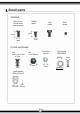
I Tools Required for the Build and Maintenance of the Car You will need following tools enabling you to build, run and maintain the model. Hex Wrench Allen Keys1.5mm, 2mm, 2.5mm Grease ,, II Flat Screwdriver Thread Lock
I Small parts SCREWS TM3X8 Hex Round Head machine screw FM3x8 screw Cap screw Grub screw -t -t 8mm 8mm l_•· -1 � �� 3mm 3mm OTHER HARDWARE ball M3*Sx0 4.7mm M3 Nylon lock nut ball Sx0 5.8mm 4.7mm ball bearing 05x010x4 05mm J � 5.8mm 3mm 3mm shock washer 03.2x07.0x0.5 -�- 03.2mm 0.
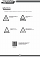
I Symbols The Manual uses Symbols periodically to instruct you on a certain aspect of the build. Apply oil to the component nearest tthe symbol Denotes either a tricky part of the assembly or a safety consideration. Apply thread locking compound to the component nearest the symbol Apply grease to the component nearest the symbol 1 A part number within a box indicates that the stage is for reference only. The parts will have been pre assembled in the factory.
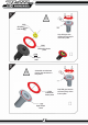
I Stage 1: Ball diff.
D D �<:> C532 05x08x�� Ball bearing "" Drip 502 glue into the slot and quickly fit the friction plate. C528 Differential friction plate C526 Left output shaft Assemble non asbestos friction plate as shown in the picture �--C528 Differential friction plate Right output shaft 5 D D D �c:, Drip 502 glue into the slot and quickly fit the friction plate.
C370 ..mi.� M2.5 Nylon locknut lllf c� Ball diff nut ------- C537 Spring 03.Bx 01.5x 6.5 D ' ���a�:� Before the installati on, add a little grease to the diff friction plate. ------------C530 Rightp� housing \ \_ C529 Left pulley housing 6 �� � So..? I I I I I I I I '----------------- Attach the left pulley housing to the right pulley housing using a few drops of 502 glue.
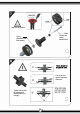
D 1. Add grease as shown in the picture. �- Assemble the components as shown, make sure the grooves face the cage. C534 Little washer A 02.5x 05.9x 1.0 C535 Little washer B C536 02.6x 06.0x 1.
r--------- Ball Diff. Add ball diff. grease �-C539 Socket cap screw M2.5x24mm C532 05x08x2.5mm Ball bearing D I-------------------, 1 :CD� I I I �: I I There should be no gaps or slop L ___________________ J I-------------------, I I I I :® I I : I I <> CT � L ___________________ J Check that the ball diff passes all 3 tests as shown on the right. 8 The diff should rotate in opposite directions.
C187 X2 010x015x 4mm Ball bearing D D 9
I Stage 2: Gearbox case Open Parts Bag B 10
C545 ______ Left drive gear housing C570 TM3x22mm Hex round head machine screw C542 Left cap C562 Adjuster D ---- C541 Right drive gear housing r C550 Adjusting wheel C552X2 Ball bearing 03x 0 6x 2.5mm C551 X 2 Washer 06x3x0.
,--- C565 Toothed Drive Belt D C3651------, Pin 01.
C572 TM3x15mm Hex round head machine screw D Left drive gear housing C79 M3 x 10mm Hexagon screw This grub screw is used to make adjustments to the belt tension.
C561 Screw ,---- Locking sleeve Cut 3mm of plastic screw to use as a locking sleeve for the 3mm machine screw. --· '----C571 TM3x5 Hex round head machine screw C571 TM3x5 Hex round head machine screw D 562 Adjuster As shown in the pictures above: 1. Do not tighten the nut completely C118 M3 Nyloc nut 2. Keep grub screw vertical.
,------------------.I C543 Gearbox housing A C186 05x010x4mm I I I I I I I '------------. ______ I C569X3 Hex round head machine screw C544 Gearbox housing B Pin 01.5x6mm D C559 ' Motor mounting plate In order to avoid the motor plate coming loose add thread lock to the 3 screw holes.
C547 C549 x 2 Slipper clutch aluminum pads Spur gear 97t Pin 01.5x6mm C548X2 --� Non-asbestos friction plate D C558 Washer 04.2x09 x8 mm 10mm c- ----� � 254 Washer 07.2x01.5 x13.5 mm 16 M4 Nyloc nut Adjust the slipper clutch as necessary for your requirements.
C31 -------... M3 Hexagon grub screw Motor pinion Grub screw must securely lock the pinion gear to the motor shaft, ensure the grub screw sits on the flat of the shaft. D 18T Flat on motor shaft ---a --...� ,,-----,- C114� Shock washer 03.2x07.0 x0.
C581 C603 TM3x12mmHex Round Head machine screw C582 --C571 1 Hex �mm head machine screw / R���d D t 2mm 1. Leave the top of the grub screw protruding about 2mm above the adjuster block. Once the gearbox assembly is complete adjust the belt tension using the adjuster grub screw 2. Press the belt with a screwdriver or similar tool and adjust until there is about 1mm movement.
I Stage 3: Chassis, Mud guard Open Parts Bag C g
C583 Chassis L------------------ C597 X4 FM3 x 8mm Hexagon countersunk machine screw C584 D C585 Servo saver set C586 C595X4 Servo saver arms Ball bearing 03x 08x3 fl D
C604X2 / TM3x10mmHex Round h ead machine / screw C587 Servo saver arms connecting plate C596X2 ---� Flanged sleeve spacers 03x 0 5.9x5.
C597 C599 FM3 x 8mm Hexa on countersunk machine =\ screw C588 FM3 x 12mm Hexagon countersunk machine screw \� Servo saver mount After assembly make sure it moves freely, do not overtighten screws.
,------------------1 I : I I I I I I I I .
C602 TM3 x 8mm Hex round head machine screw C577 Left mud guard � FM3 x 8mm Hexagon countersunk machine screw D C118 --� M3 Nyloc nut C600 ' C578 Right mud guard � FM3 x 8mm Hexagon countersunk machine screw 51 FM3 x 15mm Hexagon countersunk machine screw D
C589 C281 Upper cap for servo saver Ball st� (short) "" C592 Servo arm C593X2 Servo saver spring C590 Lower cap for servo saver(F) Servo saver spring spacer D C574X2 Servo mount C604X4 TM3 x10mm Hex round head machine screw C575X2 Servo damper C114X4 _____, D Shock washer 03.2x07.0 x0.
C601 TM2.5 x 10mm Hex round head machine screw Set the servo to its neutral position, install the servo arm then lock in place with the round head machine screw as shown.
------------------, Assemble steering rod as shown then clip to servo arm and the servo saver. 2mm C79 M3x10m Hexagon� grub ,,, .
I Stage 4: Front bulkhead Open Parts Bag D
C628X2 TM2.5 x8mm Hex round head machine screw C613 --, Adjusting set B C605X2 �susp arm / C612 Adjusting set A C602X2 TM3x8mm Hex round head machine screw Recess D Please pay attention to the direction of the recess. C609 Susp.
C617 Front susp. arm mounting C603X2 TM3x 12mm Hex round head machine screw D C627 X2 3x8mm Hexagon grub screw.
-------------- I I I I I I I I --------------1 I I I I I !.
C114X2 C622X2 Shock washer 03.2x07.0 x0.5mm Front wheel hub carrier C570X 2 �) __ TM3x22mm Hex round head machine screw C620 C627X4 Ball bearing 05x 013x4 D C596X4 Flanged sleeve spacer 03x 05.9x 5.5 C138X2 Ball stub (long) C619 Right bracket C C281X2 Ball stub B (short) � C618 Left bracket C .
C606X4 �e 03.1 x0 7 / machine screw ;1;� Please pay attention to the direction of the washer C625X2 Front susp. arm shaft 03 x34mm CD® D C607 X8 ---+ 21.
C602X3 round head machine screw C118X2 C632X2 M3 Nyloc nut FM3x25mm Hexagon countersunk machine screw D C623 Front shock C603X4 TM3x12mm Hex round head machine screw D 3
I Stage 5: Gearbox and rear bulkhead Open Parts Bag E
C603X4 TM3x12mm � csgaX4 Hex round head machine screw FM3x10mm Hexagon countersunk machine screw ,� __ ....--- Rear wing holder ... .... ...___ C643 Rear shock tower C639 Rear shock tower seat D After the assembly of rear shock tower and gearbox, please move forward to next assembly.
Drivers can adjust the screws to change the angle of the susp. arms. ,--------------1 I I I I�--�==�� I---------------- C633X2 Rear susp. arm C567 C568 TM2.5x12mm Hex round head machine screw Rear adjusting set A Rear adjusting set B D M2.5x5mm Socket cap screw C646X2 ' /searing holder pin 03.0 x50mm / �------------------I I I I I I I I I I L ________________ C644X4 Ball end for susp.
----------------------, I I I· I I I I I I I I I I I I I L _____________________ J C642 C641 Rear susp. arm mounting B Rear susp.
, C599X2 1 I I --- -·�-.. ------. ..
Please pay attention to the direction of the washers. C625X2 Front susp. arm pin 03 x34mm TM3x3.
C607 X4 ----+ 29mm +- Tie rod 03 x45mm D C637 C636 �yholder Batterycover support FM3 x10mm Hexagon countersunk machine screw C599X2 FM3x12mm Hexagon countersunk machine screw 41 D
C650 C649 Cover plate \ �reseal � ;;;;t Please pay attention to the direction of the cover plate.
C615X4 Battery holder C631 X4 FM3x20mm Hexagon countersunk machine screw C131 X4 D ,----- C616 Battery cover plate Clip-A D 4
I Stage 6: Shock assembly and installation Open Parts Bag F ¥1
C669X2 C655X8 C664X4 Spacer for 0-ring (1.8mm) Upper for shock C667 X4 Front shock cylinder body (short) C670X2 Lower cap for shock C663X4 Guard washer for 0-ring (1.1 mm) Rear shock cylinder body (long) D C659X2 J C65 Front piston ( 6 holes) Rear centra 03.5 x55.5m C658X2 Front central shaft 03.5 x48mm Rear piston ( 4 holes) 1. Please match the front and rear central shafts with front and rear cylinder bodies. Shock washer 02.606.5x0.5mm 2.
C661 X4 ,--1 I I I I I I I --... As above picture shows fit the Oring into the recess of the adjusting ring and fit to shock absorber, set to a gap of 4mm. C66BX4 Adjusting ring for shock D C653X4 Ball cup for shock C654X4 -r dS06 Do not mark the central shaft with pliers during the ball cup assembly.
--7--- C553X2 _ _/ Shock spring 016.7x67x 0 1.1mm Lower seat for shock ,___ Shock spring D C666X4 r---- 5mm 1 I I I I I I I I C662 Shock After adding 3/4 of the button shock oil gently move the cap shaft up and down several times to eliminate air bubbles. Then fill the shock body with shock oil until there is a gap of 5mm from the top (do not overfill). Screw cap into place.
C624X2 C114X2 Ball stub for shock C359X2 M3X22mm Button head screw Shock washer 03.207x0.5 mm - --�X2 M3 Nyloc nut TM3X15mm Hex ro und head machine screw C359X2 D C624X2 M3X22mm button head screw C114X2 Shock washer03.2 07x0.
I Stage 7:Tyre, Wheel, Sponge, Open Parts Bag G Rear wing
Front whe--� sponge C563X2 Front wheel ------ D '----Front tyre Rear wheel sponge--� C564X2 Rear wheel ------ '---- Rear tyre
Rear tyre completed Once the wheels and tyres have been assembled run a small amount of thin CA glue around the rims.
C671 X2 washer 010x1.
Motor Rear-mount D Motor Mid-mount D
D
BZ222-Pro spare pans list 30073-ball bearing cp5* 30075-ball bearingcplO* 30081-clip-A lOpcs cp10*4 -2pcs cpl5*4- 2pcs (SKU:A2016T-30081) (SKU:A2016T-30073) (SKU:A2016T-30075) 30083-M3 lock nutlOpcs (SKU:110BS30083) 30084-M4 lock nut 10pcs-10pcs (SKU:A2016T-30084) 30235-pin for upper susp. arm -4pcs (SKU:A2016T-30235) 30789-M2.5*24 hex screw 4pcs-10pcs (SKU:9249000166) 30832-Pins cpl.5*7mm- 30997-pin cpl.
BZ222-Pro spare pans list 33932-main drive shaft 33933-adjusting wheel, lpcs spindle, 1 pcs (SKU:9249001037-0) (SKU:9249001038-0) 33938- hub carrier washer----8pcs (SKU:9249001043-0) 33934-adjuster Block with arm 2pcs (SKU:9249001039-0) 33939- limited slip Pad- 33940-square seal 2pcs sheet-lOpcs (SKU:9249001044-0) (SKU:9249001045-0) DOD DO 33935-Drive belt 33936-tie rod-2pcs lpcs (SKU:9249001041-0) (SKU:9249001040-0) 33937-CVD complete2pcs (SKU:9249001041-0) 33942-ball bearing1j15* 33943-ball bearin
BZ222-Pro spare pans list 33989-servo saver completed-lPCS (SKU:9249001186-0) 33990-battery cover plate-lPCS (SKU:9249001187-0) 33991-T-wheel hub,M2*5 screws2PCS (SKU:9249001188-0) 33992-T-front susp.arm mounts-lPCS (SKU:9249001189-0) 33993-T-rear susp.arm 33994-T-rear susp.arm 33995-susp.
Final Checks Before you run your car, check the following. 1. Check that all the screws are fully tightened unless otherwise mentioned in the build stages. If the screws are threaded into metal parts make sure you applied thread lock to stop them coming loose. 2. Check there are no binding parts, the suspension parts should drop under their own weight (with no shock absorbers mounted). The car should also roll freely with very little effort. 3.
Safety Precautions You have in your possession a model that is capable of speeds of 30mph or more. Coupled with a weight of nearly 2 kilograms this could cause serious injury to yourself or others around you. Keep the following in mind when running your car. 1. Operate the model in open areas with no people around. You must not use your car on public roa ds, places where children are present, residential area s, indoors or in confined areas. 2.