
Instruction manual

62
Adjust Cooling Airflow -- Single Stage and High
Stage
Cooling
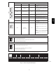
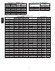
The ECM blower can be adjusted for a range of airflow for Low
Speed or High Speed cooling. See Table 7--Air Delivery -- CFM
(With Filter ). Depending on the model size, the cooling airflow
can be adjusted from 1.5 to 6 tons of nominal cooling based on
350 CFM ton.
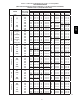
The cooling airflow is adjusted by turning AC setup switches
SW2--1, SW2--2 and SW2--3 either ON or OFF. Select the required
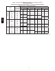
airflow from Fig. 55. Fig. 55 is based on 350 CFM per ton. For
other CFM per ton setup switch selections see Fig. 55 and Fig. 64.)
NOTE: 6 ton airflow will truncate at 2200 CFM on applicable
models. For a complete explanation of cooling airflow, refer to the
section titled “Sequence of Operation.”
4. The continuous fan airflow is adjusted by turning CF setup
switches SW3--1, 3--2 and 3--1 either ON or OFF. See Table
7 -- Air Delivery -- CFM (With Filter). Select the required
continuous fan airflow from Fig. 55.
The continuous fan speed is also the fan speed for low
speed cooling when furnace is used with a 2--speed cooling
unit. Adjust the Continuous Fan CFM to match the airflow
required for low speed cooling. Select the required airflow
from Fig. 55. For other CFM per ton setup switch selec-
tions, see Fig. 55 and Fig. 64.) The airflow selected for low
speed cooling will also be the airflow used for continuous
fan.
The continuous fan speed can be further adjusted at the ther-
mostat using the “Comfort Fan” select function. Changing
the continuous fan speed at the thermostat DOES NOT
change the low speed cooling airflow selected at the control
board.
Adjust Continuous Fan Airflow/Low Speed
Cooling
Airflow
The ECM blower motor can be adjusted for continuous fan speeds
different than heating or cooling fan speed. See Table 7--Air
Delivery -- CFM (With Filter). Select the required continuous fan
airflow from Fig. 55.
The continuous fan speed is also the fan speed for low speed
cooling when furnace is used with a 2--speed cooling unit. Adjust
the Continuous Fan CFM to match the airflow required for low
speed cooling. Select the required airflow from Fig. 55. For other
CFM per ton setup switch selections, see Fig. 55 and Fig. 64.) The
airflow selected for low speed cooling will also be the airflow used
for continuous fan.
The continuous fan speed can be further adjusted at the thermostat
using the “Comfort Fan” select function. Changing the continuous
fan speed at the thermostat DOES NOT change the low speed
cooling airflow selected at the control board.
Adjust Thermostat Heat Anticipator.
a. Mechanical thermostat. Set thermostat heat anticipator to
match the amp. draw of the electrical components in the
R--W/W1 circuit. Accurate amp. draw readings can be ob-
tained at the wires normally connected to thermostat sub-
baseterminals,R and W.Thethermostatanticipatorshould
NOT be in the circuit while measuring current.
(1.) Set SW1--2 switch on furnace control board to ON.
(2.) Remove thermostat from subbase or from wall.
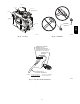
(3.) Connect an amp. meter as shown in Fig. 53 across
the R and W subbase terminals or R and W wires
at wall.
(4.) Record amp. draw across terminals when furnace is
in low heat and after blower starts.
(5.) Set heat anticipator on thermostat per thermostat
instructions and install on subbase or wall.
(6.) Turn SW1--2 switch OFF.
(7.) Install blower door.
b. Electronic thermostat: Set cycle rate for 3 cycles per hr.
Check Safety Controls
The flame sensor, gas valve, and pressure switch were all checked
in the Start--up procedure section as part of normal operation.
1. Check Main Limit Switch
This control shuts off combustion system and energizes air--
circulating blower motor, if furnace overheats. By using this
method to check limit control, it can be established that lim-
it is functioning properly and will operate if there is a re-
stricted return--air supply or motor failure. If limit control
does not function during this test, cause must be determined
and corrected.
a. Run furnace for at least 5 minutes.
b. Gradually block off return air with a piece of cardboard or
sheet metal until the limit trips.
c. Unblock return air to permit normal circulation.
d. Burners will re--light when furnace cools down.
2. Check Pressure Switch(es)
This control proves operation of the draft inducer blower.
a. Turn off 115--v power to furnace.
b. Disconnect inducer motor lead wires from wire harness.
c. Turn on 115--v power to furnace.
d. Set thermostat to “call for heat” and wait 1 minute. When
pressureswitch is functioning properly, hot surface igniter
should NOT glow and control diagnostic light flashes a
status code 32. If hot surface igniter glows when inducer
motor is disconnected, shut down furnace immediately.
e. Determine reason pressure switch did not function prop-
erly and correct condition.
f. Turn off 115--v power to furnace.
g. Reconnect inducer motor wires, replace door, and turn on
115--v power.
h. Blower will run for 90 seconds before beginning the call
for heat again.
i. Furnace should ignite normally.
Checklist
1. Put away tools and instruments. Clean up debris.
2. Verify that switches SW1--1 and SW1--6 are OFF and other
setup switches are set as desired. Verify that switches
SW1--7 and SW1--8 for the blower OFF DELAY are set as
desired per Table 17.
3. Verify that blower and control doors are properly installed.
4. Cycle test furnace with room thermostat.
5. Check operation of accessories per manufacturer’s instruc-
tions.
6. Review Owner’s Manual with owner.
7. Attach literature packet to furnace.
986TA