
Instruction manual

61
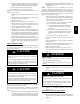
c. When correct input is obtained, replace caps that conceal
gasvalveregulator adjustment screws. Main burner flame
should be clear blue, almost transparent (See Fig. 60.)
d. Remove jumpers R to W/W1 and R to W2.
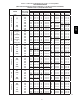
3. Verify natural gas input rate by clocking meter.
NOTE: Gas valve regulator adjustment caps must be in place for
proper input to be clocked.
a. Turn off all other gas appliances and pilots served by the
meter.
b. Movesetup switchSW1--2 toONposition. Thiskeepsfur-
nace locked in low--heat operation.
c. Jumper R to W/W1.
d. Run furnace for 3 minutes in low--heat operation.
e. Measure time (in sec) for gas meter to complete 1 revolu-
tion and note reading. The 2 or 5 cubic feet dial provides
a more accurate measurement of gas flow.
f. Refer to Table 18 for cubic ft. of gas per hr.
g. Multiply gas rate cu ft./hr by heating value (Btuh/cu ft.)
to obtain input. If clocked rate does not match required in-
put from Step 1, increase manifold pressure to increase in-
putordecreasemanifold pressuretodecreaseinput.Repeat
steps b through e until correct low--heat input is achieved.
Re--install low heat regulator seal cap on gas valve.
h. Move setup switch SW1--2 to OFF position and jumper R
to W/W1, and W2. This keeps furnace locked in high--heat
operation. Repeat items d through g for high--heat opera-
tion.
Adjust Temperature Rise
NOTE: Blower door must be installed when taking temperature
rise reading. Leaving blower door off will result in incorrect
temperature measurements.
FURNACE OVERHEATING HAZARD
Failure to follow this caution may result in shortened
furnace life.
Set air temperature rise within limits specified on the rating
plate to prevent reduced life of furnace components.
Operation is within a few degrees of the mid--point of rise
rangewhensetupswitchSW1--4isOFF.
CAUTION
!
FURNACE DAMAGE HAZARD
Failure to follow this caution may result in overheating the
heat exchangers or condensing flue gases in heat exchanger
areas not designed for condensate.
Temperature rise must be within limits specified on unit
rating plate. Operation is within a few degrees of midpoint
ofriserangewhensetupswitchSW1--4isOFF.
CAUTION
!
When setup switch SW1--4 is ON, operation will be near the high
end of the rise range for improved comfort.
Furnace must operate within ranges of temperature rise specified
on the furnace rating plate. Determine air temperature rise as
follows:
a. Place thermometers in return and supply ducts as near fur-
nace as possible. Be sure thermometers do not see heat ex-
changer so that radiant heat does not affect readings. This
practice is particularly important with straight--run ducts.
b. When thermometer readings stabilize, subtract return--air
temperature from supply--air temperature to determine air
temperature rise.
NOTE: Temperature rise can be determined for low--heat
operation by placing setup switch SW1--2 on furnace control in
ON position. For high--heat operation, place setup switch SW1--2
in OFF position and jumper R--W2 on furnace control. DO NOT
forget to return setup switch to OFF position and remove R--W2
jumper upon completion of testing.
c. This furnace is capable of automatically providing proper
airflow to maintain the temperature rise within the range
specified on furnace rating plate. If temperature rise is out-
side this range, proceed as follows:
(1.) Check gas input for low-- and high--heat operation.
(2.) Check derate for altitude if applicable.
(3.) Check all return and supply ducts for excessive
restrictions causing static pressure greater than
0.5--In. W.C.
(4.) Ensure Low Heat Rise Adjust switch SW1--3 on
furnace control is in ON position when a bypass
humidifier is used. (See Fig. 35 for switch loca-
tion.)
(5.) Make sure proper model plug is installed.
d. Remove thermostat jumpers and release blower door
switch.
e. Repeat Steps a through c as required to adjust for high heat
temperature rise.
f. When correct high heat input rate and temperature rise is
achieved, turn gas valve ON/OFF switch to OFF.
g. Release blower door switch.
h. Remove manometer or similar device from gas valve.
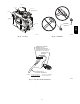
i. Re--install manifold pressure tap plug in gas valve. (See
Fig. 51.)
FIRE HAZARD
Failure to follow this warning could result in personal
injury, death, and/or property damage.
Reinstall manifold pressure tap plug in gas valve to prevent
gas leak.
!
WARNING
j. Remove thermostat jumper wire from furnace control
board.
k. Turn gas valve ON/OFF switch to ON.
FURNACE OVERHEATING HAZARD
Failure to follow this caution may result in reduced furnace
life.
Recheck temperature rise. It must be within limits specified
on the rating plate. Recommended operation is at the
mid--point of rise range or slightly above.
CAUTION
!
l. Proceed to “Set Blower Off Delay” before installing
blower door.
Adjust Blower Off Delay (Heat Mode)
a. Remove blower door if installed.
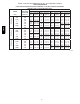
b.TurnDipswitchSW--7orSW--8ONorOFFfordesired
blower off delay. (See Table 17 and Fig. 35, Fig. 55 and
Fig. 64.)
986TA