
Instruction manual

60
FIRE OR EXPLOSION HAZARD
Failure to follow this warning could result in personal
injury, death, and/or property damage.
Never purge a gas line into a combustion chamber. Never
test for gas leaks with an open flame. Use a commercially
available soap solution made specifically for the detection
of leaks to check all connections. A fire or explosion may
result causing property damage, personal injury or loss of
life.
!
WARNING
Adjustments
FIRE HAZARD
Failure to follow this warning could result in personal
injury, death and/or property damage.
DO NOT bottom out gas valve regulator adjusting screw.
This can result in unregulated manifold pressure and result
in excess overfire and heat exchanger failures.
!
WARNING
FURNACE DAMAGE HAZARD
Failure to follow this caution may result in reduced furnace
life.
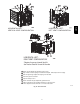
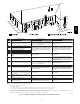
DO NOT redrill orifices. Improper drilling (burrs,
out--of--round holes, etc.) can cause excessive burner noise
and misdirection of burner flames. This can result in flame
impingement of heat exchangers, causing failures. (See Fig.
52.)
CAUTION
!
For proper operation and long term reliability, the Furnace input
rate must be within +2 percent of input rate on furnace rating plate.
The gas input rate on rating plate is for installations at altitudes up
to 2000 ft. (609.6M).
In the USA., the input rating for altitudes above 2000 ft. (609.6M)
must be reduced by 2 percent for each 1000 ft. (304.8M) above sea
level. Refer to Table 16.
In Canada, the input rating must be derated by 5 percent for
altitudes of 2000 ft. (609.6M) to 4500 ft. (1371.6M) above sea
level.
To adjust manifold pressure to obtain the proper input rate, first,
determine if the furnace has the correct orifice installed. At higher
altitudes or different gas heat contents, it may be necessary to
change the factory orifice to a different orifice. Tables have been
provided in the furnace installation instructions to match the
required orifice to the manifold pressure to the heat content and
specific gravity of the gas. To do this:
a. Obtain average yearly gas heat value (at installed altitude)
from local gas supplier.
b. Obtain average yearly gas specific gravity from local gas
supplier.
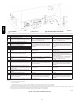
c. Find installation altitude in Table 19.
d. Find closest natural gas heat value and specific gravity in
Table 19.
e. Follow heat value and specific gravity lines to point of in-
tersection to find orifice size and low--and high--heat mani-
fold pressure settings for proper operation.
f. Check and verify burner orifice size in furnace. NEVER
ASSUME ORIFICE SIZE. ALWAYS CHECK AND
VERIFY.
NOTE: For Canadian altitudes of 2000 to 4500 ft. (609.6 to
1371.6M), use USA altitudes of 2001 to 3000 ft. (609.6 to
914.4M).
NOTE: If orifice hole appears damaged or it is suspected to have
been redrilled, check orifice hole with a numbered drill bit of
correct size. Never redrill an orifice. A burr--free and squarely
aligned orifice hole is essential for proper flame characteristics.
g. Replace orifice with correct size, if required by Table 19.
Use only factory--supplied orifices. See EXAMPLE 1.
EXAMPLE 1
EXAMPLE: 0 -- 2000 ft. (0 -- 609.6M) altitude
Heating value = 1050 Btu/cu ft.
Specific gravity = 0.62
Therefore: Orifice No. 44
Manifold pressure: 3.4--in. w.c. for high heat, 1.4--in. w.c. for low
heat
* Furnace is shipped with No. 44 orifices. In this example, all main
burner orifices are the correct size and do not need to be changed to
obtain proper input rate.
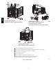
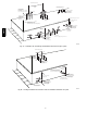
1. Adjust manifold pressure to obtain low fire input rate. (See
Fig. 51.)
a. Turn gas valve ON/OFF switch to OFF.
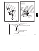
b. Remove manifold pressure tap plug from gas valve.
c. Connect a water column manometer or similar device to
manifold pressure tap.
d. Turn gas valve ON/OFF switch to ON.
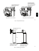
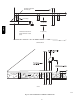
e. Move setup SW1—2 on furnace control to ON position to
lock furnace in low--heat operation. (See Fig. 55 and Fig.
35.)
f. Manually close blower door switch.
g. Jumper R and W/W1 thermostat connections on control to
start furnace. (See Fig. 35.)
h. Remove regulator adjustment cap from low heat gas valve
pressureregulator (See Fig. 51.) and turn low--heat adjust-
ing screw (3/16 or smaller flat--tipped screwdriver) coun-
terclockwise (out) to decrease input rate or clockwise (in)
to increase input rate.
NOTE: DO NOT set low--heat manifold pressure less than 1.3--in.
W.C. or more than 1.7--In. W.C. for natural gas. If manifold
pressure is outside this range, change main burner orifices.
i. Install low--heat regulator adjustment cap.
j. Move setup switch SW1--2 to off position after completing
low--heat adjustment.
k. Leave manometer or similar device connected and proceed
to Step 4.
2. Adjust manifold pressure to obtain high fire input rate. (See
Fig. 51.)
a. Jumper R to W/W1 and W2 thermostat connections on fur-
nace control. This keeps furnace locked in high--heat oper-
ation.
b. Remove regulator adjustment cap from high--heat gas
valve pressure regulator (See Fig. 51) and turn high heat
adjusting screw (3/16--in. or smaller flat--tipped screw-
driver) counterclockwise (out) to decrease input rate or
clockwise (in) to increase input rate.
NOTE: DO NOT set high--heat manifold pressure less than
3.2--In. W.C. or more than 3.8 In. W.C. for natural gas. If manifold
pressure is outside this range, change main burner orifices to obtain
manifold pressure in this range.
986TA