
Instruction manual

59
START--UP, ADJUSTMENT, AND SAFETY
CHECK
General
1. Furnace must have a 115-v power supply properly connec-
ted and grounded.
NOTE: Proper polarity must be maintained for 115-v wiring.
Control status indicator light flashes rapidly and furnace does not
operate if polarity is incorrect.
2. Thermostat wire connections at terminals R, W/W1, G, and
Y/Y2 must be made at 24-v terminal block on furnace con-
trol.
3. Natural gas service pressure must not exceed 0.5 psig (14-
in. w.c.), but must be no less than 0.16 psig (4.5-in. w.c.).
4. Blower door must be in place to complete 115-v electrical
circuit to furnace.
UNIT OPERATION HAZARD
Failure to follow this caution may result in intermittent unit
operation or performance satisfaction.
These furnaces are equipped with a manual reset limit
switch in burner assembly. This switch opens and shuts off
power to the gas valve is an overheat condition (flame
rollout) occurs in burner assembly. Correct inadequate
combustion--air supply or improper venting condition
before resetting switch. DO NOT jumper this switch.
CAUTION
!
Before operating furnace, check flame rollout manual reset switch
for continuity. If necessary, press button to reset switch.
EAC-1 terminal is energized whenever blower operates. HUM
terminal is only energized when blower is energized in heating.
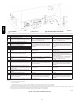
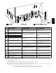
Select Setup Switch Positions
There are four sets of setup switches on the furnace control board.
These switches configure the furnace for correct application
requirement. They also select the airflow settings for Air
Conditioning and Continuous Fan CFMs.
The Setup Switch locations are shown and described on Fig. 55.
The set up switches are also shown on the unit wiring label.
Setup Switches (SW1)
The furnace control has 8 setup switches that may be set to meet
the application requirements. To set these setup switches for the
appropriate requirement:
S Remove blower door.
S Locate setup switches on furnace control.
S Configure the set-up switches as necessary for the application.
S Replace blower door.
NOTE: If a bypass humidifier is used, setup switch SW1-3 (Low
Heat Rise Adjust) should be in ON position. This compensates for
the increased temperature in return air resulting from bypass.
Air Conditioning (A/C) Setup Switches (SW2)
The air conditioning setup switches are used to match furnace
airflow to cooling unit used.
To set the desired cooling airflow:
1. Remove blower door.
2. Locate A/C setup switches on furnace control.
3. Determine air conditioning tonnage used.
4. Configure the switches for the required cooling airflow.
NOTE: Excessive airflow caused by improper A/C switch setup
may cause condensate blow-off in cooling mode.
5. Replace blower door.
Continuous Fan (CF) Setup Switches (SW3)
The CF setup switches are used to select desired airflow when
thermostat is in continuous fan mode or to select low-cooling
airflow for two-speed cooling units. This setup feature allows
continuous fan airflow or low-cooling airflow to be adjusted. To
set desired continuous fan airflow or low-cooling airflow:
1. Remove blower door.
2. Locate CF setup switches on furnace control.
3. Determine desired continuous fan airflow or low-cooling
airflow.
4. Configure the switches for the required continuous fan or
low--cooling airflow.
5. Replace blower door.
Setup Switch (SW4)
Setup switches SW4 are used for applications using a
communicating User Interface and to adjust airflow. Refer to the
communicating User Interface instructions for configuration of
SW4 for communications. Refer to Fig. 55 for configuration of
SW4 airflow options.
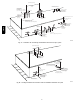
Prime Condensate Trap with Water
UNIT OPERATION HAZARD
Failure to follow this caution may result in intermittent unit
operation or performance satisfaction.
Condensate trap must be PRIMED or proper draining may
not occur. The condensate trap has two internal chambers
which can ONLY be primed by pouring water into the
inducer drain side of condensate trap.
CAUTION
!
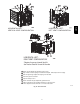
1. Remove upper and middle collector box drain plugs oppos-
ite of the condensate trap. (See Fig. 58.)
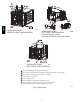
2. Connect field-supplied 1/2-in. (13 mm) OD tube to upper
collector box drain connection.
3. Insert field-supplied funnel into tube.
4. Pour one quart of water into funnel/tube. Water should run
through collector box, overfill condensate trap, and flow in-
to open field drain.
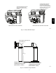
5. Remove funnel; replace collector box drain plug.
6. Connect field-supplied 1/2-in. (13 mm) OD tube to middle
collector box drain port.
7. Pour one quart of water into funnel/tube. Water should run
through collector box, overfill condensate trap, and flow in-
to open field drain.
8. Remove funnel and tube from collector box and replace col-
lector box drain plug.
Purge Gas Lines
If not previously done, purge the lines after all connections have
been made and check for leaks.
986TA