
Instruction manual

54
V
V
Item
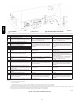
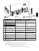
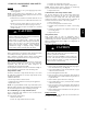
Clearance Description Canadian Installation (1) U.S. Installation (2)
A
Clearance above grade, veranda, porch, deck, bal-
cony or anticipated snow level
12 in. (305 mm). 18 in. (457 mm) above roof surface. 12 in. (305 mm)
B Clearance to a window or door that may be opened
12 in. (305 mm) for appliances > 10,000 Btuh (3kW)
and </--- 100,000 Btuh (30 kW), 36 in. (914 mm) for
appliances > 100,000 Btuh (30 kW)
9 in. (229 mm) for appliances > 10,000 Btuh (3kW)
and </--- 50,000 Btuh (15 kW), 12 in. (305 mm) for
appliances > 500,000 Btuh (15 kW)
C Clearance to a permanently closed window
For clearances not specified in ANSI Z223.1/NFPA 54 or
C A N / CSA B149.1, clearances shall be in accordance
with local installation codes and the requirements of
the gas supplier and the manufacturer’s installation
instructions.
For clearances not specified in ANSI Z223.1/NFPA 54 or
C A N / CSA B149.1, clearances shall be in accordance
with local installation codes and the requirements of
the gas supplier and the manufacturer’s installation
instructions.
D
Vertical clearance to a ventilated soffit located above
the terminal within a horizontal distance of 2 feet (61
cm) from the centerline of the terminal
E Clearance to an unventilated soffit
F Clearance to an outside corner
G Clearancetoaninsidecorner
H
Clearance to each side of the centerline extended
above electrical meter or gas service regulator as-
sembly
3ft.(.9M)within15ft. (4.6 M) abovethemeter/
regulator assembly
3ft.(.9M)within15ft. (4.6 M) abovethemeter/
regulator assembly
I Clearance to service regulator vent outlet 3ft.(.9M)
*3 ft. (.9 M) *For clearances not specified in ANSI Z223.1
/NFPA 54or C A N / CSA B149.1, clearances shall be in
accordance with local installation codes and the
requirements of the gas supplier and the manufacturer’s
installation instructions.
J
Clearance to non---mechanical air supply inlet to
building or the combustion air inlet to any other appli-
ance
12 in. (305 mm) for appliances > 10,000 Btuh(3kW)
and </--- 100,000 Btuh (30 kW), 36 in. (914 mm) for
appliances > 100,000 Btuh (30 kW)
9 in. (229 mm) for appliances > 10,000 Btuh (3kW)
and </--- 50,000 Btuh (15 kW), 12 in. (305 mm) for
appliances > 500,000 Btuh (15 kW)
K Clearance to a mechanical air supply inlet 6ft.(1.8M) 3ft.(.9M)
L Clearance under a veranda, porch, deck, or balcony
12 in. (305 mm). Permitted only if veranda, porch,
deck, or balcony is fully open on a minimum of two
sides beneath the floor.
For clearances not specified in ANSI Z223.1/NFPA 54 or
C A N / CSA B149.1, clearances shall be in accordance
with local installation codes and the requirements of
the gas supplier and the manufacturer’s installation
instructions.
M
Clearance to each side of the centerline extended
above or below vent terminal of the furnace to a dryer
or water heater vent, or other appliance’s direct vent
intake or exhaust
12 in. (305 mm) 12 in. (305 mm)
N
Clearance to the vent terminal of a dryer vent, water
heater vent, or other appliances direct vent intake or
exhaust
3ft.(.9M) 3ft.(.9M)
O Clearance from a plumbing vent stack 3ft.(.9M) 3ft.(.9M)
P
Clearance above paved sidewalk or paved driveway
located on public property
7 ft. (2.1 M). A vent shall not terminate above a side-
walk or paved driveway that is located between two
single family dwellings and serves both dwellings.
For clearances not specified in ANSI Z223.1/NFPA 54 or
CAN/CSA B149.1, clearances shall be in accordance
with local installation codes and the requirements of
the gas supplier and the manufacturer’s installation
instructions.
(1) In accordance with the current C A N / CSA B
149.1, Natural Gas and Propane Installation Code.
(2) In accordance with the current ANSI Z223.1.NFPA 54, National Fuel Gas Code
Notes:
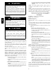
1. The vent for this appliance shall not terminate:
a. Over public walkways; or
b. Near soffit vents of crawl space vents or other areas where condensate or vapor could create a nuisance or hazard or property damage; or
c. Where condensate vapor could cause damage or could be detrimental to the operation of regulators, relief valves, or other equipment.
2. When locating vent terminations, consideration must be given to prevailing winds, location, and other conditions which may cause recirculation of the combustion products of adjacent vents.
Recirculation can cause poor combustion, inlet condensate problems, and accelerated corrosion of the heat exchangers.
3. Avoid venting under a deck or large overhang. Recirculation could occur and cause performance or system problems.
A11046
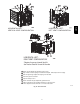
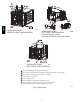
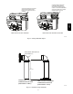
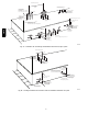
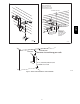
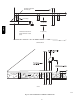
Fig. 45 -- Direct Vent Termination Clearance
986TA