
Instruction manual

41
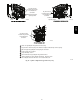
Allowable vent and combustion air terminations are shown in Fig.
47.
Ventilated Combustion Air
The vent pipe for a Ventilated Combustion Air System must
terminate outdoors. Follow all vent termination clearances shown
in Fig. 46. Allowable vent terminations are shown in Fig. 48. The
combustion air pipe terminates in a well--ventilated attic or crawl
space. Follow the clearances as shown in Fig. 50.
The combustion air pipe cannot terminate in attics or crawl spaces
that use ventilation fans designed to operate in the heating season.
If ventilation fans are present in these areas, the combustion air
pipe must terminate outdoors as a Direct Vent System.
Non-Direct Vent / 1-Pipe System
The vent pipe for a Non Direct Vent (1--pipe) system must
terminate outdoors. Follow all vent termination clearances shown
in Fig. 46. Allowable vent terminations are shown in Fig. 48.
A combustion air pipe to the outdoors is not required for a
Non--Direct Vent System. A 12--inch long section of pipe with a
tight radius 2--in. (50.8 mm) 90 degree elbow is required to be
attached to the furnace.
Termination Requirements for the Provinces of Alberta and
Saskatchewan
The Provinces of Alberta and Saskatchewan require a minimum
unobstructed distance of 4 ft. (1.2 M) from the foundation to the
property line of the adjacent lot for vent termination of any
appliance with an input over 35,000 btuh. If there is less than 4 ft.
(1.2 M) of unobstructed distance to the property line of the
adjacent lot, no type of vent termination is permitted for appliances
with inputs greater than 35,000 btuh.
There are no additional restrictions on unobstructed distances
greater than 8 ft. (2.4 M). All single, two-pipe and concentric vents
may be used, providing all other Code and manufacturer’s
requirements in these instructions are adhered to. Refer to the
appropriate Vent Termination section above for locating the vent
termination
If the unobstructed distance from the foundation to the property
line of the adjacent lot is no less than 4 ft. (1.2 M) and no greater
than 8 ft. (2.4 M), it will be necessary to re-direct the flue gas
plume. In this situation, a concentric vent kit cannot be used. A
2-pipe termination (or single pipe termination when permitted) that
re-directs the flue gas away by use of an elbow or tee, certified to
ULC S636 from the adjacent property line must be used. See Fig.
49.
The concentric vent kit currently cannot be modified to attach an
elbow to the vent portion of the rain cap. A tee attached to the rain
cap could potentially direct the flue gas plume toward the intake air
stream and contaminate the incoming combustion air for the
furnace.
Refer to Fig. 49 for terminations approved for use in Alberta and
Saskatchewan.
Size the Vent and Combustion Air Pipes
General
Furnace combustion air and vent pipe connections are sized for
2-in. (51 mm) pipe. Any pipe diameter change should be made
outside furnace casing in vertical pipe. Any change is diameter to
the pipe must be made as close to the furnace as reasonably
possible.
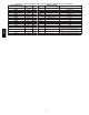
The Maximum Vent Length for the vent and combustion air pipe
(when used) is determined from the Maximum Equivalent Vent
Length in Table 13 or 15, minus the number of fittings multiplied
by the deduction for each type of fitting used from Table 14.
The measured length of pipe used in a single or 2--pipe termination
is included in the total vent length. Include a deduction for a Tee
when used for Alberta and Saskatchewan terminations. Concentric
vent terminations, pipe lengths or elbows do not require a
deduction from the Maximum Equivalent Vent Length.
1. Measure the individual distance from the furnace to the ter-
mination for each pipe.
2. Select a Maximum Equivalent Vent Length (MEVL) longer
than the measured distance of the individual vent and com-
bustion air connections to the vent termination.
3. Count the number of elbows for each pipe.
4. For each pipe, multiply the number of elbows by the equi-
valent length for the type of elbow used. Record the equi-
valent length of all the elbows for each pipe.
5. If a Tee is used on the termination, record the equivalent
length of the Tee used.
6. Record the equivalent length of the termination to be used.
7. Subtract the equivalent lengths of the fittings and termina-
tions from the Maximum Equivalent Vent Length.
8. If the Maximum Vent Length calculated is longer than the
individual measured length of the vent pipe and combustion
air pipe, then the diameter of pipe selected may be used.
9. If the Maximum Vent Length calculated is shorter than the
individual measured length of either the vent pipe or the
combustion air pipe, recalculate the Maximum Vent Length
using the next larger diameter pipe.
NOTE: The vent pipe and combustion air pipe must be the same
diameter.
NOTE: If the Maximum Vent Length for diameter of the pipe
selected is longer than the measured length and the equivalent
length of all the fitting and terminations, recalculate using the next
smaller diameter. If the recalculated Maximum Vent Length is
longer than the measured length of the vent pipe and combustion
air pipe, then that diameter of pipe selected may be used.
When installing vent systems of short pipe lengths, use the smallest
allowable pipe diameter. Do not use pipe size greater than required
or incomplete combustion, flame disturbance, or flame sense
lockout may occur.
Combustion Air and Vent Piping Insulation
Guidelines
NOTE: Use closed cell, neoprene insulation or equivalent.
The vent pipe may pass through unconditioned areas. The amount
of exposed pipe allowed is shown in Table 12.
1. Using winter design temperature (used in load calculations),
find appropriate temperature for your application and fur-
nace model.
2. Determine the amount of total and exposed vent pipe.
3. Determine required insulation thickness for exposed pipe
length(s).
4. When combustion air inlet piping is installed above a sus-
pended ceiling, the pipe MUST be insulated with moisture
resistant insulation such as Armaflex or other equivalent
type of insulation.
5. Insulate combustion air inlet piping when run in warm, hu-
mid spaces.
6. Install the insulation per the insulation manufacturer’s in-
stallation instructions.
NOTE: Pipe length (ft. / M) specified for maximum pipe lengths
located in unconditioned spaces cannot exceed total allowable pipe
length as calculated from Table 13 or 15.
986TA