
Instruction manual

29
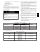
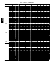
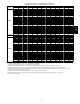
Table 7 -- Air Delivery -- CFM (With Filter) (Continued)
(SW1-5 and SW4-3 set to OFF, except as indicated. See Notes 1 and 2.)
INPUT
BTUH
Cooling Switch Settings External Static Pressure (E.S.P.)
SW2-3 SW2-2 SW2-1 0.1 0.2 0.3 0.4 0.5 0.6 0.7 0.8 0.9 1.0
100000
OFF OFF OFF 2115 2035 1965 1890 1805 1725 1625 1540 1435 1345
OFF OFF ON 870 715 585 525 450
OFF ON OFF 1025 950 900 835 770
OFF ON ON 1210 1165 1105 1055 1000 950 895 845 800 735
ON OFF OFF 1400 1355 1295 1250 1205 1155 1110 1060 1020 960
ON OFF ON 1615 1570 1525 1485 1435 1395 1345 1310 1260 1210
ON ON OFF 2115 2035 1965 1890 1805 1725 1625 1540 1435 1345
ON ON ON 2115 2035 1965 1890 1805 1725 1625 1540 1435 1345
Maximum Cooling Airflow
2
2115 2035 1965 1890 1805 1725 1625 1540 1435 1345
High Heat Airflow
3
2115 2035 1965 1890 1805 1725 1625 1540 1435 1345
Low Heat Airflow
3
1575 1530 1485 1445 1395 1350 1305 1265 1215 1165
INPUT
BTUH
Cooling Switch Settings External Static Pressure (E.S.P.)
SW2-3 SW2-2 SW2-1 0.1 0.2 0.3 0.4 0.5 0.6 0.7 0.8 0.9 1.0
120000
6
OFF OFF OFF 2010 1960 1910 1850 1800 1750 1690 1645 1565 1480
OFF OFF ON 1015 805 645 550 480
OFF ON OFF 1075 975 915 835 765
OFF ON ON 1205 1135 1055 1000 935
ON OFF OFF 1400 1330 1260 1190 1145 1080 1035 970 905 845
ON OFF ON 1615 1550 1500 1435 1370 1325 1265 1215 1160 1110
ON ON OFF 2010 1960 1910 1850 1800 1750 1690 1645 1565 1480
ON ON ON note 7 2375 2300 2205 2115 2010 1890 1750 1645 1550
Maximum Cooling Airflow
2
note 7 2375 2300 2205 2115 2010 1890 1750 1645 1550
High Heat Airflow
3
note 7 2375 2300 2205 2115 2010 1890 1750 1645 1550
Low Heat Airflow
3
1735 1675 1625 1560 1500 1455 1395 1345 1285 1225
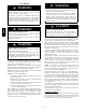
1. Nominal 350 CFM/ton cooling airflow is delivered with SW1-5 and SW4-3 set to OFF.
Set both SW1-5 and SW4-3 to ON for +7% airflow (nominal 370 CFM/ton).
Set SW1-5 to ON and SW4-3 to OFF f or +15% airflow (nominal 400 CFM/ton).
Set SW4-3 to ON and SW1-5 to OFF for -7% airflow (nominal 325 CFM/ton).
2. Maximum cooling airf low is a ch ieved when switches SW3-1, SW3-2, SW3-3 a nd SW1-5 are set to ON, and SW4-3 is set to OFF.
3. All heating CFM's are when low heat rise adjustment switch (SW1-3) and comfort/efficiency adjustment switch (SW1-4) are both set to OFF.
4. Ductwork must be sized for high-heating CFM within the operational range of E.S.P. Operation within the blank areas of the chart is not recommended
because high-heat operation will be above 1.0 E.S.P.
5. All airflows on 21" (533 mm) casing size furnaces are 5% less on side return only installations.
6. Side returns for 24.5" (622 mm) casing sizes require two sides, or side and bottom, to allow sufficient airflow at the return of the furnace.
7. Airflow not stable at this E.S.P.
986TA