
Instruction manual

20
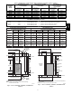
1. Determine application being installed from Table 6.
2. Construct hole in floor per Table 6andFig. 19.
3. Construct plenum to dimensions specified in Table 6and
Fig. 19.
4. Install special base coil assembly or coil box as shown in in
Fig. 19.
CUT HAZARD
Failure to follow this caution may result in personal injury.
Sheet metal parts may have sharp edges or burrs. Use care
and wear appropriate protective clothing, safety glasses and
gloves when handling parts, and servicing furnaces.
CAUTION
!
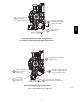
NOTE: It is recommended that the perforated supply--air duct
flanges be completely removed from furnace when installing the
furnace on a factory--supplied cased coil or coil box. To remove the
supply--air duct flange, use wide duct pliers or hand seamers to
bend flange back and forth until it breaks off. Be careful of sharp
edges. (See Fig. 20.)
Connect supply--air duct to supply--air outlet on furnace. Bend
flange inward past 90_ with wide duct pliers (See Fig. 20.) The
supply--air duct must be connected to ONLY the furnace supply
outlet or air conditioning coil casing (when used). When installed
on combustible material, supply--air duct must be connected to
ONLY the factory--approved accessory subbase, or a
factory--approved air conditioning coil casing. DO NOT cut main
furnace casing to attach supply side air duct, humidifier, or other
accessories. All accessories MUST be connected to duct external to
furnace casing.
Return Air Connections
FIRE HAZARD
A failure to follow this warning could cause personal injury,
death and/or property damage.
Never connect return--air ducts to the back of the furnace.
Follow instructions below.
!
WARNING
The return--air duct must be connected to return--air opening
(bottom inlet). DO NOT cut into casing sides (left or right).
Bypass humidifier connections should be made at ductwork or coil
casing sides exterior to furnace. (See Fig. 25.)
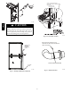
Bottom Return Air Inlet
These furnaces are shipped with bottom closure panel installed in
bottom return--air opening. Remove and discard this panel when
bottom return air is used. To remove bottom closure panel, perform
the following:
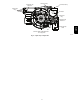
1. Tilt or raise furnace and remove 4 screws holding bottom
plate. (See Fig. 22.)
2. Remove bottom plate.
3. Remove bottom closure panel.
4. Reinstall bottom plate and screws.
Horizontal Installation
NOTE: The furnace must be pitched forward as shown in Fig. 23
for proper condensate drainage.
FIRE, EXPLOSION, AND CARBON MONOXIDE
POISONING HAZARD
Failure to follow this warning could result in personal
injury, death, or property damage.
Do not install the furnace on its back or hang furnace with
control compartment facing downward. Safety control
operation will be adversely affected. Never connect
return--air ducts to the back of the furnace.
!
WARNING
The furnace can be installed horizontally in an attic or crawlspace
on either the left--hand (LH) or right--hand (RH) side. The furnace
can be hung from floor joists, rafters or trusses or installed on a
non--combustible platform, blocks, bricks or pad.
Platform Furnace Support
Construct working platform at location where all required furnace
clearances are met. (See Table 2andFig. 27.) For furnaces with
1--in. (25 mm) clearance requirement on side, set furnace on
non--combustible blocks, bricks or angle iron. For crawlspace
installations, if the furnace is not suspended from the floor joists,
the ground underneath furnace must be level and the furnace set on
blocks or bricks.
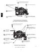
Suspended Furnace Support
The furnace must be supported under the entire length of the
furnace with threaded rod and angle iron. (See Fig. 28.) Secure
angle iron to bottom of furnace as shown.
Roll--Out Protection
Provide a minimum 12--in. x 22--in. (305 x 559 mm) piece of sheet
metal for flame roll--out protection in front of burner area for
furnaces closer than 12--in. (305 mm) above the combustible deck
or suspended furnaces closer than 12--in. (305 mm) to joists. The
sheet metal MUST extend underneath the furnace casing by 1--in.
(25 mm) with the door removed.
The bottom closure panel on furnaces of widths 17--1/2--in. (445
mm) and larger may be used for flame roll--out protection when
bottom of furnace is used for return air connection. See Fig. 27 for
proper orientation of roll--out shield.
Supply Air Connections
For a furnace not equipped with a cooling coil, the outlet duct shall
be provided with a removable access panel. This opening shall be
accessible when the furnace is installed and shall be of such a size
that the heat exchanger can be viewed for possible openings using
light assistance or a probe can be inserted for sampling the air
stream. The cover attachment shall prevent leaks.
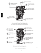
Connect supply--air duct to flanges on furnace supply--air outlet.
Bend flange upward to 90_ with wide duct pliers. (See Fig. 20.)
The supply--air duct must be connected to ONLY the furnace
supply--outlet--air duct flanges or air conditioning coil casing
(when used). DO NOT cut main furnace casing side to attach
supply air duct, humidifier, or other accessories. All accessories
MUST be connected to duct external to furnace main casing.
Return Air Connections
The return--air duct must be connected to bottom of the furnace.
The side of casing that faces downward may also be used for return
air connection. A combination of the bottom and downward
facing side may also be used. The side of the casing cannot be
used as a return air connection. Bypass humidifier may be attached
into unused return air side of the furnace casing. (See Fig. 26.)
Bottom Return Air Inlet
These furnaces are shipped with bottom closure panel installed in
bottom return--air opening. Remove and discard this panel when
bottom return air is used. To remove bottom closure panel, perform
the following:
986TA