
Instruction manual

19
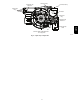
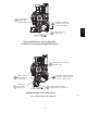
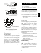
LEFT SIDE DRAIN ROUTED BEHIND INDUCER
TRAP, DRAIN ELBOW WITH DISCHARGE PIPE
Attach tube to condensate trap
Cut formed end o
condensate drain tube
Connect short end
of “Z” pipe to modied
drain tube
Field supplied 1/2” CPVC
coupling & drain extension
17 1/2“, 21” and 24 1/2” casing
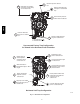
Field supplied 1/2”
CPVC to drain
Casing grommet from
loose parts bag
Modied drain tube connect to
condensate trap and “Z” pipe
Field-supplied 1/2” CPVC coupling & drain
pipe 17 1/2“, 21” and 24 1/2” casings
A11344
Fig. 16 -- Drain Trap Connection and Routing
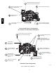
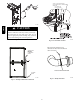
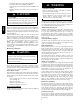
Remove knockout.
Install grommet before
relocating condensate
trap.
A11348
Fig. 17 -- Horizontal Drain Trap Grommet
INSTALLATION
Upflow Installation
NOTE: The furnace must be pitched forward as shown in Fig. 23
for proper condensate drainage.
Supply Air Connections
For a furnace not equipped with a cooling coil, the outlet duct shall
be provided with a removable access panel. This opening shall be
accessible when the furnace is installed and shall be of such a size
that the heat exchanger can be viewed for possible openings using
light assistance or a probe can be inserted for sampling the air
stream. The cover attachment shall prevent leaks.
Connect supply--air duct to flanges on furnace supply--air outlet.
Bend flange upward to 90_ with wide duct pliers. (See Fig. 20.)
The supply--air duct must be connected to ONLY the furnace
supply--outlet--air duct flanges or air conditioning coil casing
(when used). DO NOT cut main furnace casing side to attach
supply air duct, humidifier, or other accessories. All accessories
MUST be connected to duct external to furnace main casing.
Return Air Connections
FIRE HAZARD
A failure to follow this warning could cause personal injury,
death and/or property damage.
Never connect return--air ducts to the back of the furnace.
Follow instructions below.
!
WARNING
The return--air duct must be connected to bottom, sides (left or
right), or a combination of bottom and side(s) of main furnace
casing. Bypass humidifier may be attached into unused return air
side of the furnace casing. (See Fig. 24, 25, 26.)
Bottom Return Air Inlet
These furnaces are shipped with bottom closure panel installed in
bottom return--air opening. Remove and discard this panel when
bottom return air is used. To remove bottom closure panel, perform
the following:
1. Tilt or raise furnace and remove 4 screws holding bottom
plate. (See Fig. 22.)
2. Remove bottom plate.
3. Remove bottom closure panel.
4. Reinstall bottom plate and screws.
Side Return Air Inlet
These furnaces are shipped with bottom closure panel installed in
bottom return--air opening. This panel MUST be in place when
only side return air is used.
NOTE: Side return--air openings can be used in UPFLOW and
some HORIZONTAL configurations. Do not use side return--air
openings in DOWNFLOW configuration. (See Fig. 24, 25, 26.)
Leveling Legs (If Desired)
In upflow position with side return inlet(s), leveling legs may be
used. (See Fig. 21.) Install field--supplied, 5/16 x 1--1/2 in. (8 x 38
mm) (max) corrosion--resistant machine bolts, washers and nuts.
NOTE: Bottom closure must be used when leveling legs are used.
It may be necessary to remove and reinstall bottom closure panel to
install leveling legs. To remove bottom closure panel, see Item 1 in
Bottom Return Air Inlet section in Step 1 above.
To install leveling legs:
1. Position furnace on its back. Locate and drill a hole in each
bottom corner of furnace.
2. For each leg, install nut on bolt and then install bolt with
nut in hole. (Install flat washer if desired.)
3. Install another nut on other side of furnace base. (Install flat
washer if desired.)
4. Adjust outside nut to provide desired height, and tighten in-
side nut to secure arrangement.
5. Reinstall bottom closure panel if removed.
Downflow Installation
NOTE: The furnace must be pitched forward as shown in Fig. 23
for proper condensate drainage.
Supply Air Connections
NOTE: For downflow applications, this furnace is approved for
use on combustible flooring when any one of the following 3
accessories are used:
S Special Base, KGASB
S Cased Coil Assembly Part No. CNPV, CNRV, CAP, or CAR
S Coil Box Part No. KCAKC
986TA