
Instruction manual

12
CONDENSATE TRAP
Condensate Trap -- Upflow Orientation
When the furnace is installed in the upflow position, it is not
necessary to relocate the condensate trap or associated tubing.
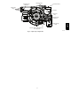
Refer to Fig. 8 for upflow condensate trap information. Refer to
Condensate Drain section for information how to install the
condensate drain.
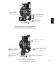
Condensate Trap -- Downflow Orientation.
When the furnace is installed in the downflow position, the
factory-installed trap will be located at the upper left corner of the
collector box. When the furnace is installed in the downflow
orientation, the factory-installed trap must be relocated for proper
condensate drainage.
To Relocate the Condensate Trap:
S Orient the furnace in the downflow position.
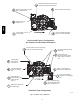
S Fig. 9 shows the condensate trap and tubing before and after
relocation.
S Remove the relief tube from the condensate trap.
S Remove the screw that secures the condensate trap to the
collector box.
S Remove the trap.
S Remove the relief tube from the port on the collector box. It is
not necessary to remove the tube from the inducer assembly.
S Remove the pressure switch tube from the front pressure switch
and discard the tube. A new pressure switch tube is shipped in
the loose parts bag.
S Loosen the clamp around the inlet of the vent elbow on the
inducer.
S Remove the middle and bottom plugs from the lower right side
of the collector box and set aside. Do Not Discard Plugs.
S Refer to the appropriate figure to begin the trap conversion.
S Install the 2 plugs previously removed from the collector box in
the ports where the condensate trap was removed.
S Install the trap over the ports on the lower right side of the
collector box.
S Secure the trap to the collector box with the screw.
S Connect the relief tube to the condensate trap to the relief port of
the condensate trap.
S If necessary, slide the relief tube in the inducer stand-offs to
adjust the position of the tube.
S Connect the relief tube to the relief port of the condensate trap.
S Connect the new pressure switch tube to the port on the front
pressure switch. Route the tube through the stand-offs on the
inducer assembly and connect to the port on the collector box.
Trim off any excess tube to avoid sags or kinks in the tube.
S Rotate the vent elbow to the desired position and tighten the
clamp 15 in.-lbs.
S Refer to Condensate Drain section for information how to install
the condensate drain.
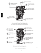
Condensate Trap -- Horizontal Orientation.
When the furnace is installed in the horizontal right position, the
factory-installed trap will be located at the bottom of the collector
box. When the furnace is installed in the horizontal left position,
the factory-installed trap will be located at the top of the collector
box. The trap must be repositioned on the collector box for proper
condensate drainage.
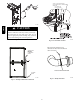
When the furnace is installed as a direct--vent furnace, a field
supplied, accessory Horizontal Installation Kit is required for all
horizontal installations. The kit contains a rubber Casing Grommet
designed to seal between the furnace casing and the condensate
trap. (See Fig. 17 ).
NOTE: The condensate trap extends below the side of the casing
in the horizontal position. A minimum of 2 inches (51 mm) of
clearance is required between the casing side and the furnace
platform for the trap to extend out of the casing in the horizontal
position.
To Relocate the Condensate Trap:
S Remove the knockout in the casing for the Casing Grommet.
S Install the grommet in the casing.
S Orient the furnace in the desired position.
S Allow for 2 inches (51 mm) of clearance underneath the furnace
for the condensate trap and drain line.
S Fig. 10 shows the condensate trap and tubing before and after
relocation in the horizontal right position.
S Fig. 11 shows the condensate trap and tubing before and after
relocation in the horizontal left position.
S Refer to the appropriate figure to begin the trap conversion.
S Remove the relief tube from the condensate trap.
S Remove the screw that secures the condensate trap to the
collector box.
S Remove the trap.
S Remove the relief tube from the port on the collector box. It is
not necessary to remove the tube from the inducer assembly.
For Horizontal Left only:
S Remove the pressure switch tube from the front pressure switch and
discard the tube. A new pressure switch tube is shipped in the loose
parts bag.
For Horizontal Right only:
S The pressure switch tube location is not modified.
S Loosen the clamp around the inlet of the vent elbow on the inducer.
S Remove the plugs from the collector box and set aside. Do Not
Discard Plugs.
For Horizontal Left only:
S Remove the middle and right plug from the ports at the bottom
of the collector box.
For Horizontal Right only:
S Remove the plug to the right of the condensate trap.
S Refer to the appropriate figure to begin the trap conversion.
S Install the plugs previously removed from the collector box in
the ports where the condensate trap was removed.
S Install the trap over the ports on the lower side of the collector
box.
S Secure the trap to the collector box with the screw.
S Connect the relief tube to the condensate trap to the relief port of
the condensate trap.
S If necessary, slide the relief tube in the inducer stand-offs to
adjust the position of the tube.
S Connect the relief tube to the relief port of the condensate trap.
For Horizontal Left only:
S Connect the new pressure switch tube to the port on the front
pressure switch. Route the tube through the stand-offs on the
inducer assembly and connect to the port on the collector box.
Trim off any excess tube to avoid sags or kinks in the tube.
S Rotate the vent elbow to the desired position and tighten the
clamp 15 in.-lbs.
S Refer to Condensate Drain section for information how to install
the condensate drain.
986TA