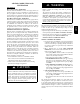
986TA TWO--STAGE VARIABLE--SPEED ECM MULTIPOISE GAS FURNACE SERIES 100/A Installation, Start--up, Operating and Service and Maintenance Instructions NOTE: Read the entire instruction manual before starting the installation. Checklist . . . . . . . . . . . . . . . . . . . . . . . . . . . . . . . . . . . . . . . . 62 SAFETY CONSIDERATIONS . . . . . . . . . . . . . . . . . . . . . . . . . 3 SERVICE AND MAINTENANCE PROCEDURES . . . . . . . . 69 Cleaning Heat Exchangers . . . . . . . . . . . . . . . . . . .
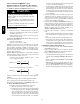
Required Notice for Massachusetts Installations 986TA IMPORTANT The Commonwealth of Massachusetts requires compliance with regulation 248 CMR as follows: 5.08: Modifications to NFPA--54, Chapter 10 2) Revise 10.8.3 by adding the following additional requirements: a.
! WARNING FIRE, EXPLOSION, ELECTRICAL SHOCK, AND CARBON MONOXIDE POISONING HAZARD Failure to follow this warning could result in dangerous operation, personal injury, death, or property damage. Improper installation, adjustment, alteration, service, maintenance, or use can cause carbon monoxide poisoning, explosion, fire, electrical shock, or other conditions which may cause personal injury or property damage.
986TA INTRODUCTION This 4--way multipoise Category IV condensing furnace is CSA design--certified as a direct (2-pipe) or non-direct vent (1-pipe) furnace. (See Fig. 2.)The furnace is factory--shipped for use with natural gas. The furnace can be converted in the field for use with propane gas when a factory-supplied conversion kit is used. Refer to the furnace rating plate for conversion kit information. This furnace is not approved for installation in mobile homes, recreational vehicles, or outdoors.
ACCESSORIES See Product Data Sheet for a list of accessories for this product LOCATION ! CAUTION wood flooring (refer to SAFETY CONSIDERATIONS). S be located close to the chimney or vent and attached to an air distribution system. Refer to Air Ducts section. S be provided ample space for servicing and cleaning. Always comply with minimum fire protection clearances shown in Table 2 or on the furnace clearance to combustible construction label.
! WARNING ! WARNING FIRE, INJURY OR DEATH HAZARD FIRE HAZARD Failure to follow this warning could result in personal injury, death and/or property damage. Failure to follow this warning could result in personal injury, death and/or property damage. When the furnace is installed in a residential garage, the burners and ignition sources must be located at least 18 in. (457 mm) above the floor. The furnace must be located or protected to avoid damage by vehicles.
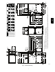
Fig. 1 -- Dimensional Drawing A11525 7 AIR FLOW 19 1/8 [485.8] 21 [534.0] 26 5/16 [668.8] 22 [558.3] SIDE INLET 7/8 [22.2] 7/8 [22.2] THERMOSTAT ENTRY CONDENSATE DRAIN TRAP LOCATION 1 [25.4] 7/8 [22.2] 17 5/16 [439.2] 20 1/4 [513.9] 28 3/16 [715.9] 048100 066120 A 35 [889.0] 30 7/16 [773.7] 28 3/8 [720.4] 3 [76.2] AIR INTAKE 1 5/16 [33.3] 28 3/4 [730.5] 29 1/2 [749.3] 14 13/16 [376.3] 16 9/16 [420.9] 25 3/16 [639.1] 22 15/16 [581.9] 28 5/8 [726.4] 11/16 [17.5] 32 5/8 [829.
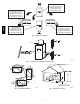
THE BLOWER IS LOCATED BELOW THE BURNER SECTION, AND CONDITIONED AIR IS DISCHARGED UPWARD. 986TA THE BLOWER IS LOCATED TO THE RIGHT OF THE BURNER SECTION, AND AIR CONDITIONED AIR IS DISCHARGED TO THE LEFT. THE BLOWER IS LOCATED TO THE LEFT OF THE BURNER SECTION, AND CONDITIONED AIR IS DISCHARGED TO THE RIGHT. THE BLOWER IS LOCATED ABOVE THE BURNER SECTION, AND CONDITIONED AIR IS DISCHARGED DOWNWARD A02097 Fig. 2 -- Multipoise Orientations 80 / 27˚C SUPPLY AIR 60 / 16˚C A10490 Fig.
AIR FOR COMBUSTION AND VENTILATION ! WARNING Introduction CARBON MONOXIDE POISONING HAZARD Direct Vent (2-- pipe) Applications Failure to follow this warning could result in personal injury or death. When the furnace is installed as a direct vent (2-pipe) furnace, no special provisions for air for combustion are required. However, other gas appliances installed in the space with the furnace may require outside air for combustion.
Indoor Combustion AirE NFPA & AGA Standard and Known-- Air-- Infiltration Rate Methods of the floor. The minimum dimension of air openings shall be at least 3 in. (80 mm). (See Fig. 7.) c. Combining space on different floor levels. The volumes of spaces on different floor levels shall be considered as communicating spaces if connected by one or more permanent openings in doors or floors having free area of at least 2 in.2/1,000 Btuh (4,400 mm2/kW) of total input rating of all gas appliances. 2.
Table 3 – Minimum Free Area Required for Each Combustion Air Opening or Duct to Outdoors TWO HORIZONTAL DUCTS (1 SQ. IN./2,000 BTUH) (1,100 SQ. MM/KW) FURNACE INPUT (BTUH) SINGLE DUCT OR OPENING (1 SQ. IN./3,000 BTUH) (734 SQ. MM/KW) Free Area of Opening and Duct Sq. In (Sq. mm) Round Duct In. (mm) Dia 20 (12904) 30 (19355) TWO OPENINGS OR VERTICAL DUCTS (1 SQ. IN./4,000 BTUH) (550 SQ. MM/KW) Free Area of OpenRound Duct ing and Duct In. (mm) Dia. Sq. In (mm) Free Area of Opening and Duct Sq. In (Sq.
CONDENSATE TRAP Condensate Trap -- Upflow Orientation When the furnace is installed in the upflow position, it is not necessary to relocate the condensate trap or associated tubing. Refer to Fig. 8 for upflow condensate trap information. Refer to Condensate Drain section for information how to install the condensate drain. 986TA Condensate Trap -- Downflow Orientation.
Vent Pipe Clamp Condensate Trap Relief Port Vent Elbow Clamp Collector Box Plugs Vent Elbow Collector Box Plug Condensate Trap Relief Port Condensate Trap Outlet 986TA Pressure Switch Port UPFLOW TRAP CONFIGURATION 1 & 2 Stage Units A11307 Fig.
Remove pressure switch tube from front pressure switch and discard. Remove relief tube from relief port on collector trap. Remove tube from relief port. 986TA Remove trap from collector box. Loosen clamp on inlet to vent elbow. Remove middle and bottom plugs. DO NOT DISCARD. Unconverted Factory Configuration As Viewed in the Downflow Orientation Connect tube from Loose Parts bag to port on front pressure switch. Route tube through inducer stand-offs. Trim excess tube.
Remove plug from collector box. DO NOT DISCARD. 986TA If alternate vent position is required, loosen clamp on inlet of vent elbow. Remove trap from collector box. Unconverted Factory Trap Configuration As Viewed in the Horizontal Right Orientation Slide relief tube in stand-offs to adjust length. Vent elbow shown in alternate orientation. Tighten clamp on inlet to vent elbow 15 lb.-in. Attach condensate trap with screw to collector box. Install plug in open port on collector box.
5 Remove trap from collector box. If alternate vent position is required, loosen clamp on vent elbow inlet. Remove relief tube from relief port on condensate trap. 986TA Remove front pressure switch tube and discard. Remove relief tube from port on collector box. Remove middle and right plug from collector box. 6 Unconverted Factory Trap Configuration As Viewed in the Horizontal Left Orientation 9 Install plug in open ports on collector box.
Upflow/Downflow Orientation 9. 10. In the Upflow or Downflow orientation, the condensate trap is inside the furnace casing. The condensate drain must be routed from the trap through the furnace casing. The condensate drain can be routed through the left or right side of the casing. (The left or right side is as you are viewing the furnace.) The furnace condensate drain can be connected to the Air Conditioning condensate drain as shown in Fig. 13.
INSTALL CLAMPS ON DRAIN TUBE ATTACH DRAIN TUBE TO CONDENSATE DRAIN TRAP PULL DRAIN STUB THROUGH CASING 986TA A11305 CAUTION ! CUT HAZARD Failure to follow this caution may result in personal injury. Sheet metal parts may have sharp edges or burrs. Use care and wear appropriate protective clothing, safety glasses and gloves when handling parts, and servicing furnaces. A11342 Fig. 12 -- Knockout Removal Fig.
Return Air Connections Attach tube to condensate trap Cut formed end off condensate drain tube Field supplied 1/2” CPVC coupling & drain extension 17 1/2“, 21” and 24 1/2” casing ! Connect short end of “Z” pipe to modified drain tube WARNING FIRE HAZARD A failure to follow this warning could cause personal injury, death and/or property damage. TRAP, DRAIN ELBOW WITH DISCHARGE PIPE Never connect return--air ducts to the back of the furnace. Follow instructions below.
1. Determine application being installed from Table 6. 2. Construct hole in floor per Table 6 and Fig. 19. 3. Construct plenum to dimensions specified in Table 6 and Fig. 19. 4. Install special base coil assembly or coil box as shown in in Fig. 19. ! ! FIRE, EXPLOSION, AND CARBON MONOXIDE POISONING HAZARD Failure to follow this warning could result in personal injury, death, or property damage. CAUTION Do not install the furnace on its back or hang furnace with control compartment facing downward.
Filter Arrangement ! WARNING FIRE, CARBON MONOXIDE AND POISONING HAZARD Failure to follow this warning could result in fire, personal injury or death. Never operate a furnace without a filter or filtration device installed. Never operate a furnace with filter or filtration device access doors removed. There are no provisions for an internal filter rack in these furnaces. An external filter is required. The furnace is shipped with a factory-supplied Media Filter Cabinet.
21-in. Furnace 14-3/16 and 17-1/2-in. Furnace 4-in. Block Off Plate 4-Ton or less, AC capacity airflow 1/2-in. Screws 20-in. Media Cabinet 986TA 16-in. Media Cabinet Media Cabinet Installation Side Return Media Cabinet Installation Option for 4-Ton or Less A/C Capacity 21- or 24-1/2-in. Furnace 21-in. Furnace up to 5-Ton AC Capacity Up to 5-Ton AC capacity airflow 24-1/2-in. Furnace up to 4-Ton AC Capacity 20- or 24-in. Media Cabinet 45° Bottom Return Plenum Transition 20- or 24-in.
FURNACE (OR COIL CASING WHEN USED) FURNACE APPROVED COIL ASSEMBLY OR COIL BOX COMBUSTIBLE FLOORING COMBUSTIBLE FLOORING A PLENUM OPENING D DOWNFLOW SUBBASE FLOOR OPENING SHEET METAL PLENUM SHEET METAL PLENUM FLOOR OPENING C FLOOR OPENING A10491 Fig. 19 -- Installation on Combustible Flooring Table 6 – Opening Dimensions -- In. (mm) FURNACE CASING WIDTH IN.
UPFLOW PERFORATED DISCHARGE DUCT FLANGE DOWNFLOW HORIZONTAL 90° 90° YES YES YES 986TA 120° MIN YES 120° MIN YES YES 120° MIN NO NO NO A10493 Fig. 20 -- Duct Flanges 5/ 16″ (8mm) (8mm) 5/ 16″ 1 3/4″ (44mm) 1 3/4″ (44mm) (8mm) 5/16″ BOTTOM CLOSURE PANEL (8mm) 5/ 16″ (44mm) 1 3/ 4″ 3/ (44mm) 1 4″ BOTTOM PLATE A89014 A11092 Fig. 21 -- Leveling Legs Fig. 22 -- Removing Bottom Closure Panel LEVEL 0-IN. (0 MM) TO 1/2-IN. (13 MM) MAX MIN 1/4-IN. (6 MM) TO 1/2-IN.
986TA ANY COMBINATION OF 1, 2, OR 3 PERMITTED. A11036 A11037 Fig. 24 -- Upflow Return Air Configurations and Restrictions Fig. 25 -- Downflow Return Air Configurations and Restrictions HORIZONTAL TOP RETURN NOT PERMITTED FOR ANY MODEL A11038 Fig.
COMBUSTION - AIR PIPE (SEE VENTING SECTION) 30 IN. (762 mm) MIN. WORK AREA 986TA 2-IN. (51 mm) ROLLOUT PROTECTION REQUIRED Install 12” x 22” (305 x 559 mm) sheet metal in front of burner compartment area. A11154 Fig. 27 -- Working Platform for Attic Installation COMBUSTION-AIR PIPE (SEE VENTING SECTION) 2-IN. (51 mm) A11155 Fig.
AIR DUCTS General Requirements 986TA The duct system should be designed and sized according to accepted national standards such as those published by: Air Conditioning Contractors Association (ACCA), Sheet Metal and Air Conditioning Contractors National Association (SMACNA) or American Society of Heating, Refrigerating and Air Conditioning Engineers (ASHRAE) or consult The Air Systems Design Guidelines reference tables available from your local distributor.
Table 7 – Air Delivery -- CFM (With Filter) (SW1-5 and SW4-3 set to OFF, except as indicated. See Notes 1 and 2.) INPUT BTUH 986TA 40000 INPUT BTUH 60000 INPUT BTUH 80000 Cooling Switch Settings SW2-3 SW2-2 SW2-1 0.1 0.2 0.3 External Static Pressure (E.S.P.) 0.4 0.5 0.6 0.7 0.8 0.9 1.
Table 7 -- Air Delivery -- CFM (With Filter) (Continued) INPUT BTUH 100000 Cooling Switch Settings SW2-3 SW2-2 SW2-1 1200006 0.2 0.3 External Static Pressure (E.S.P.) 0.4 0.5 0.6 0.7 OFF OFF OFF 2115 2035 1965 1890 1805 OFF OFF ON 870 715 585 525 450 OFF ON OFF 1025 950 900 835 770 OFF ON ON 1210 1165 1105 1055 ON OFF OFF 1400 1355 1295 ON OFF ON 1615 1570 ON ON OFF 2115 ON ON ON 0.8 0.9 1.
GAS PIPING ! ! WARNING FIRE OR EXPLOSION HAZARD A failure to follow this warning could result in personal injury, death, and/or property damage. FIRE OR EXPLOSION HAZARD Failure to follow this warning could result in personal injury, death, and/or property damage. If local codes allow the use of a flexible gas appliance connector, always use a new listed connector. Do not use a connector which has previously served another gas appliance.
Table 8 – Maximum Capacity of Pipe LENGTH OF PIPE --- FT (M) 10 (3.0) 20 (6.0) 30 (9.1) 40 (12.1) 50 (15.2) 175 360 680 1400 2100 120 250 465 950 1460 97 200 375 770 1180 82 170 320 660 990 73 151 285 580 900 ! ELECTRICAL SHOCK AND FIRE HAZARD Failure to follow this warning could result in personal injury, death, or property damage.
J--Box Installation ! 3. Secure power cord to J--Box bracket with a strain relief bushing or a connector approved for the type of cord used. 4. Pull furnace power wires through 1/2--in. (12 mm) diameter hole in J--Box. If necessary, loosen power wires from strain—relief wire--tie on furnace wiring harness. 5. Connect field ground wire and factory ground wire to green ground screw on J--Box mounting bracket as shown in Fig. 31. 6.
986TA Connect an accessory 24 VAC, 0.5 amp. maximum humidifier (if used) to the ¼--in. male quick--connect HUM terminal and COM--24V screw terminal on the control board thermostat strip. NOTE: If the humidifier has its own 24 VAC power supply, an isolation relay may be required. Connect the 24 VAC coil of the isolation relay to the HUM and COM/24V screw terminal on the control board thermostat strip. (See Fig. 33.) 3.
Table 9 – Electrical Data UNIT SIZE VOLTS--HERTZ--PHASE 40,000 60,000 80,000 100,000 120,000 115--- 60--- 1 115--- 60--- 1 115--- 60--- 1 115--- 60--- 1 115--- 60--- 1 TWO---STAGE PWM FURNACES OPERATING VOLTAGE MAXIMUM UNIT RANGE* UNIT AMPACITY# AMPS Maximum* Minimum* 127 127 127 127 127 104 104 104 104 104 8.2 9.8 9.8 12.3 12.3 11.0 13.0 13.0 16.1 16.1 MINIMUM WIRE SIZE AWG 14 14 14 12 12 MAXIMUM WIRE LENGTH FT (M)} 33 (10.0) 28 (8.5) 28 (8.5) 35 (10.6) 35 (10.
To HUM Terminal On To Humidifier Leads Furnace Control Board 24 V Coil To Humidifier Leads To Com/24V Screw Terminal on Thermostat Strip A11157 986TA Fig.
COMMUNICATION CONNECTOR MODEL PLUG CONNECTOR CONTINUOUS FAN (CF) AIRFLOW SETUP SWITCHES OUTDOOR AIR TEMP CONNECTOR SW4 SETUP SWITCHES SW1 SETUP SWITCHES AND BLOWER OFFDELAY AIR CONDITIONING (A/C) AIRFLOW SETUP SWITCHES 986TA HUMIDIFIER TERMINAL (24-VAC 0.5 AMP MAX.
THERMOSTAT THERMOSTAT D 986TA D 11, and 16 15, and 16 Modulating and 2-Stage Furnace with Single-Speed Heat Pump Modulating and 2-Stage Furnace with Single-Speed Air Conditioner THERMOSTAT THERMOSTAT D D 15, and 16 12 and 16 Modulating and 2-Stage Furnace with Two-Speed Air Conditioner Modulating and 2-Stage Furnace with Two-Speed Heat Pump A11274 Fig.
986TA NOTES FOR THERMOSTAT WIRING DIAGRAMS 1. Heat pump MUST have a high pressure switch for dual fuel applications. 2. Refer to outdoor equipment Installation Instructions for additional information and setup procedure. 3. If the heat pump date code is 1501E or earlier, select the “ZONE” position on the two speed heat pump control. Heat pumps with date code 1601E and later do not have or require a “ZONE” selection. 4. Outdoor Air Temperature Sensor must be attached in all dual fuel applications. 5.
Furnace is set in place in the required orientation. Special Venting Requirements for Installations in Canada Les autorité es ayant juridiction (inspecteurs de gas, inspecteurs en bâtiments, département des incendies, etc) devraient être consultées avant l’installation afin de déterminer si un permis est requis. ! Installation in Canada must conform to the requirements of CAN/CSA B149 code. Vent systems must be composed of pipe, fittings, cements, and primers listed to ULC S636.
A furnace shall not be connected to a chimney flue serving a separate appliance designed to burn solid fuel. Other gas appliances with their own venting system may also use the abandoned chimney as a raceway providing it is permitted by local code, the current edition of the National Fuel Gas Code and the vent or liner manufacturer’s installation instructions. Care must be taken to prevent the exhaust gases from one appliance from contaminating the combustion air of other gas appliances.
Ventilated Combustion Air The vent pipe for a Ventilated Combustion Air System must terminate outdoors. Follow all vent termination clearances shown in Fig. 46. Allowable vent terminations are shown in Fig. 48. The combustion air pipe terminates in a well--ventilated attic or crawl space. Follow the clearances as shown in Fig. 50. The combustion air pipe cannot terminate in attics or crawl spaces that use ventilation fans designed to operate in the heating season.
Configure the Furnace ! WARNING CARBON MONOXIDE POISONING HAZARD Failure to follow this warning could result in personal injury or death. 986TA To route the vent pipe and combustion air pipe through the furnace, the manufacturer supplied kit must be used. Failure to properly seal the blower compartment from the furnace vestibule could result in the circulation of carbon monoxide throughout the structure.
Installing the Vent Termination Roof Terminations A roof termination of any type will require a 4-in. (102 mm) flashing for a 2 inch (51 mm) concentric vent or a 5--in. diameter (127 mm) flashing for a 3-inch (76 mm) concentric vent kit. For two-pipe or single pipe vent systems, a flashing for each pipe of the required diameter will be necessary. It is recommended that the flashing be installed by a roofer or competent professional prior to installing the concentric vent.
Table 11 – Approved Combustion-Air and Vent Pipe, Fitting and Cement Materials (U.S.A.
Table 12 – Maximum Allowable Exposed Vent Lengths Insulation Table -- Ft. / M Maximum Length of Uninsulated and Insulated Vent Pipe-Ft (M) Winter Design Temp °F (°C) 20 (-10) 0 (-20) 40000** -20 (-30) -40 (-40) 20 (-10) 0 (-20) 60000 -20 (-30) -40 (-40) 20 (-10) 0 (-20) 80000 -20 (-30) -40 (-40) 20 (-10) 0 (-20) 100000 -20 (-30) -40 (-40) 20 (-10) 0 (-20) 120000 -20 (-30) -40 (-40) No Insulation Pipe Length in Ft. & M 3/8-in. (9.5 mm) Pipe Diameter-inches (mm) 1/2-in. (12.
NOTE: Maximum Equivalent Vent Length (MEVL) does NOT include elbows or terminations. Use Table 14 - Deductions from Maximum Equivalent Vent Length to determine allowable vent length for each application. Table 13 – Maximum Equivalent Vent Length -- Ft. (M) 0 to 4500 Ft. (0 to 1370 M) Altitude Altitude FT (M) Unit Size BTU/Hr DIRECT VENT (2-PIPE) AND NON---DIRECT VENT (1---PIPE) Vent Pipe Diameter (in.
NOTE: Maximum Equivalent Vent Length (MEVL) does NOT include elbows or terminations. Use Table 14 - Deductions from Maximum Equivalent Vent Length to determine allowable vent length for each application. Table 15 – Maximum Equivalent Vent Length -- Ft. (M) 4501 to 10,000 Ft.
986TA Attach gaskets to vent pipe and combustion air adapters. Vent Coupling and Adapter A11314 Fig. 37 -- Vent Coupling and Adapter with Gaskets INDUCER OUTLET VENT ELBOW CLAMP TORQUE 15 LB-IN. VENT PIPE CLAMP TORQUE 15 LB-IN. PSC INDUCER ASSEMBLY VENT ELBOW INDUCER OUTLET CHOKE 40,000 BTUH MODELS ONLY A11285 Fig.
7 6 4 5 Any other unused knockout may be used for combustion air connection. Rotate vent elbow to required position. 3 2 & 5 Rotate vent elbow to required position. A11309 6 1 2 5 3 4 5 A11308 3 7 2 5 986TA 1 7 6 Any other unused knockout may be used for combustion air connection. 1 Any other unused knockout may be used for combustion air connection. 4 5 A11310 1 Attach vent pipe adapter with gasket to furnace casing. 2 Align notches in rubber coupling over standoffs on adapter.
3 Rotate vent elbow to required position. 2 5 4 1 Rotate vent elbow to required position. 5 4 5 1 2 5 3 Any other unused knockout may be used for combustion air connection. 6 7 6 A11311 7 986TA A11312 A11313 Downflow Vertical Requires Accessory Internal Vent Kit. See Product Data for current kit number. 1 Attach vent pipe adapter with gasket to furnace casing. 2 Align notches in rubber coupling over standoffs on adapter. Slide clamps over the coupling.
HORIZONTAL LEFT LEFT VENT CONFIGURATION HORIZONTAL LEFT RIGHT VENT CONFIGURATION* *Requires Accessory Internal Vent Kit See Product Data for Current Kit Number 1 Attach vent pipe adapter with gasket to furnace casing. 2 Align notches in rubber coupling over standoffs on adapter. Slide clamps over the coupling. 3 Slide vent pipe through adapter and coupling into vent elbow. 4 Insert vent pipe into vent elbow. 5 Torque all clamps 15 lb.-in. 6 Attach combustion air pipe adapter with gasket to furnace.
986TA HORIZONTAL RIGHT VERTICAL VENT CONFIGURATION HORIZONTAL RIGHT LEFT VENT CONFIGURATION* *Requires Internal Vent Kit See Product Data for Current Kit Number HORIZONTAL RIGHT RIGHT VENT CONFIGURATION 1 Attach vent pipe adapter with gasket to furnace casing. 2 Align notches in rubber coupling over standoffs on adapter. Slide clamps over the coupling. 3 Slide vent pipe through adapter and coupling into vent elbow. 4 Insert vent pipe into vent elbow. 5 Torque all clamps 15 lb.-in.
ALIGN NOTCHES IN VENT PIPE COUPLING OVER STAND-OFF ON ADAPTER. TORQUE LOWER CLAMP 15 LB-IN. WHEN REMAINING VENT PIPE IS INSTALLED, TORQUE UPPER CLAMP TO 15 LB-IN. 986TA VENT PIPE ADAPTER WITH GASKET INSTALLED ON FURNACE VENT PIPE IS CUT FLUSH WITH TOP OF ADAPTER. VENT PIPE FLUSH WITH ADAPTER VENT PIPE FLUSH SHOWING COUPLING A11339 Fig. 43 -- Vent Pipe Flush with Adaptor Point elbow down towards back of furnace 12” 256.
V 986TA V Item A Clearance Description Clearance above grade, veranda, porch, deck, balcony or anticipated snow level B Clearance to a window or door that may be opened C Clearance to a permanently closed window Vertical clearance to a ventilated soffit located above the terminal within a horizontal distance of 2 feet (61 cm) from the centerline of the terminal D E F G H Clearance to an unventilated soffit Clearance to an outside corner Clearance to an inside corner Clearance to each side of the c
986TA Item A Clearance Description Clearance above grade, veranda, porch, deck, balcony or anticipated snow level B Clearance to a window or door that may be opened C Clearance to a permanently closed window Vertical clearance to a ventilated soffit located above the terminal within a horizontal distance of 2 feet (61 cm) from the centerline of the terminal D E F G H Clearance to an unventilated soffit Clearance to an outside corner Clearance to an inside corner Clearance to each side of the centerli
Roof Te rmination (Preferred) At least 36 in. (914mm) Concentric Vent and Combustion Air Roof Termination (preferred) A Ve r tical separation between combustion air and vent 8 3/4 in. (222mm)f or 3 in. (76mm)ki t 6 3/4 in. (172mm)for 2 in. (51mm) ki t 18 in. maximum (457mm) A At least 36 in. (914mm) Maintain 12 in. (305mm)min. clearance above highest anticipated snow level Maximum of 24 in.(614mm) above roof Maintain 12 in. (305mm) min.
NOTE: This illustration is for reference only. Your unit may differ in appearance or may not include all components shown. OVERHANG OR ROOF VENT Angle 22.5 o to 45 o off wall BRACKET COUPLING COMBUSTION-AIR (ELBOW PARALLEL TO WALL) 986TA 12 IN. SEPARATION BETWEEN BOTTOM OF COMBUSTION AIR AND BOTTOM OF VENT MAINTAIN 12 IN. CLEARANCE ABOVE HIGHEST ANTICIPATED SNOW LEVEL OR GRADE, WHICHEVER IS GREATER. L10F022 EXHAUST OVERHANG Clearance to overhang per code 12 in. (304.8mm) MIN.
Ventilated Combustion Air intake pipe Pipe hangar 986TA 3” (76 mm) 12” (305 mm) Ventilated Combustion Air intake termination in crawl space CRAWL SPACE highest level of insulation ATTIC A10497 Fig.
General 1. Furnace must have a 115-v power supply properly connected and grounded. NOTE: Proper polarity must be maintained for 115-v wiring. Control status indicator light flashes rapidly and furnace does not operate if polarity is incorrect. 2. Thermostat wire connections at terminals R, W/W1, G, and Y/Y2 must be made at 24-v terminal block on furnace control. 3. Natural gas service pressure must not exceed 0.5 psig (14in. w.c.), but must be no less than 0.16 psig (4.5-in. w.c.). 4.
! WARNING FIRE OR EXPLOSION HAZARD Failure to follow this warning could result in personal injury, death, and/or property damage. Never purge a gas line into a combustion chamber. Never test for gas leaks with an open flame. Use a commercially available soap solution made specifically for the detection of leaks to check all connections. A fire or explosion may result causing property damage, personal injury or loss of life.
Adjust Temperature Rise NOTE: Blower door must be installed when taking temperature rise reading. Leaving blower door off will result in incorrect temperature measurements. ! CAUTION b. When thermometer readings stabilize, subtract return--air temperature from supply--air temperature to determine air temperature rise. NOTE: Temperature rise can be determined for low--heat operation by placing setup switch SW1--2 on furnace control in ON position.
986TA Adjust Cooling Airflow -- Single Stage and High Stage Cooling The ECM blower can be adjusted for a range of airflow for Low Speed or High Speed cooling. See Table 7--Air Delivery -- CFM (With Filter ). Depending on the model size, the cooling airflow can be adjusted from 1.5 to 6 tons of nominal cooling based on 350 CFM ton. The cooling airflow is adjusted by turning AC setup switches SW2--1, SW2--2 and SW2--3 either ON or OFF. Select the required airflow from Fig. 55. Fig.
TWO-STAGE ON/OFF Switch Regulator Seal Cap Regulator Adjustment Regulator Seal Cap under Cap 1/2” NPT Inlet 1/8” NPT Inlet Pressure Tap BURNER ORIFICE 986TA 1/2” NPT Outlet 1/8” NPT Manifold Pressure Tap A11152 A93059 Fig. 51 -- Gas Valve Fig. 52 -- Orifice Hole THERMOSTAT SUBBASE TERMINALS WITH THERMOSTAT REMOVED (ANITICIPATOR, CLOCK, ETC., MUST BE OUT OF CIRCUIT.) HOOK-AROUND AMMETER R Y W G 10 TURNS FROM UNIT 24-V CONTROL TERMINALS EXAMPLE: 5.0 AMPS ON AMMETER 10 TURNS AROUND JAWS = 0.
986TA A11250B_A2X96 Fig.
Furnace Setup Switch Description SWITCH NAME NORMAL POSITION DESCRIPTION OF USE Turn ON to retrieve T i up to 7 stored d status codes d ffor troubleshooting assistance when R thermostat lead is disconnected. When SW1-2 is OFF allows low heat operation with a single stage thermostat. Turn ON when using twostage thermostat to allow Low Heat operation when R to W/W1 closes and High Heat operation when R to W/W1 and W2 close. Turn ON to increase Low Heat airflow by 18 percent.
Table 17 – Blower Off Delay Setup Switch Table 16 – Altitude Derate Multiplier for U.S.A. ALTITUDE FT. M 0–2000 2001–3000 3001–4000 4001–5000 5001–6000 6001–7000 7001–8000 8001–9000 9001–10,000 0---610 610---914 914---1219 1219---1524 1524---1829 1829---2134 2134---2438 2438---2743 2743---3048 PERCENT OF DERATE 0 4--- 6 6--- 8 8--- 10 10--- 12 12--- 14 14--- 16 16--- 18 18--- 20 DERATE MULTIPLIER FACTOR* 1.00 0.95 0.93 0.91 0.89 0.87 0.85 0.83 0.81 DESIRED HEATING MODE BLOWER OFF DELAY (SEC.
Table 19 – Orifice Size and Manifold Pressure (In. W.C.) for Gas Input Rate TWO-STAGE FURNACE (TABULATED DATA BASED ON 20,000 BTUH HIGH-HEAT / 13,000 BTUH LOW-HEAT PER BURNER, DERATED 2%/1000 FT (305M) ABOVE SEA LEVEL) AVG. GAS RANGE HEAT VALUE AT ALTITUDE U.S.A. and Canada ft (m) U.S.A. and Canada U.S.A. Only U.S.A. Only 0.62 0.64 No. High/Low No. High/Low No. High/Low No. High/Low 900 43 3.8 / 1.6 42 3.2 / 1.4 42 3.3 / 1.4 42 3.4 / 1.4 0 925 43 3.6 / 1.5 43 3.7 / 1.6 43 3.
Table 19 -- Orifice Size and Manifold Pressure (In. W.C.) for Gas Input Rate (Continued) TWO-STAGE FURNACE (TABULATED DATA BASED ON 20,000 BTUH HIGH-HEAT / 13,000 BTUH LOW-HEAT PER BURNER, DERATED 2%/1000 FT (305M) ABOVE SEA LEVEL) ALTITUDE AVG. GAS RANGE HEAT VALUE AT ALTITUDE U.S.A. Only ft (m) U.S.A. Only U.S.A. Only 0.60 0.62 0.64 Orifice Mnfld Press Orifice Mnfld Press Orifice Mnfld Press Orifice Mnfld Press (Btu/cu ft) No. High/Low No. High/Low No. High/Low No.
! Electrical Controls and Wiring ! WARNING ELECTRICAL SHOCK HAZARD Failure to follow this warning could result in personal injury or death. FIRE, INJURY OR DEATH HAZARD Failure to follow this warning could result in personal injury, death and/or property damage. The ability to properly perform maintenance on this equipment requires certain knowledge, mechanical skills, tools, and equipment.
2. 3. 4. 5. 6. 7. Turn Setup Switch, SW1--1 “ON.” Manually close blower door switch. Control will flash up to 7 Status Codes. The last Status Code, or 8th Code, will be Code 11. Turn SW1--1 “OFF.” A continuously--lit Amber LED will appear and indicates proper operation. 8. Release blower door switch, install blower door and refer to the SERVICE label on the blower door for more information.
Cleaning and/or Replacing Air Filter The air filter type may vary depending on the application or orientation. The filter is external to the furnace casing. There are no provisions for an internal filter with this furnace. See “Filter Arrangement” under the “Installation” section of this manual. ! WARNING CARBON MONOXIDE POISONING AND FIRE HAZARD Failure to follow this warning could result in personal injury, death and/or property damage.
15. Reconnect blower leads to furnace control. Refer to furnace wiring diagram, and connect thermostat leads if previously disconnected. NOTE: Be sure to attach ground wire and reconnect blower harness plugs to blower motor. ! WARNING ELECTRICAL OPERATION HAZARD Failure to follow this warning could result in personal injury or death. 986TA Blower door switch opens 115--v power to control. No component operation can occur unless switch is closed.
Flushing Collector Box and Drainage System ! FIRE OR EXPLOSION HAZARD Failure to follow this warning could result in personal injury, death, and/or property damage. ELECTRICAL SHOCK AND FIRE HAZARD Failure to follow this warning could result in personal injury, death, and/or property damage. Never purge a gas line into a combustion chamber. Never test for gas leaks with an open flame. Use a commercially available soap solution made specifically for the detection of leaks to check all connections.
986TA 12. Shake trap dry. 13. Clean port on collector box with a small wire. To re-install Condensate Drain and Trap: 1. Remove adhesive backing from condensate trap gasket 2. Install gasket on collector box 3. Align the condensate trap with the drain opening on the collector box and secure the trap with the screw 4. Attach the relief hose to the relief port on the condensate trap and collector box. 5. Secure tubing to prevent any sags or traps in the tubing. 6.
Secondary Heat Exchangers 13. When furnace is re--started, flush condensate pump with clear water to check for proper operation before re--starting furnace. 14. Propylene glycol need not be removed before re--starting furnace. The condensing side (inside) of the secondary heat exchanger CANNOT be serviced or inspected without complete removal of the heat exchanger assembly. Detailed information on heat exchanger removal can be obtained from your Distributor. Wiring Diagrams See Fig.
Burner Flame Burner 986TA Manifold A11273 A89020 Fig. 59 -- Cleaning Heat Exchanger Cell Fig. 60 -- Burner Flame A11347 Fig.
IGNITER BURNER SUPT. ASSY BRACKET, IGNITER 986TA BURNER ASSY FLAME ROLLOUT SWITCH FLAME SENSOR (BELOW BURNER) A11403 Fig. 62 -- Burner Assembly SEQUENCE OF OPERATION NOTE: Furnace control must be grounded for proper operation or else control will lock out. Control is grounded through green/yellow wire routed to gas valve and burner box screw. Using the schematic diagram in Fig. 64, follow the sequence of operation through the different modes. Read and follow the wiring diagram very carefully.
b. 986TA c. d. e. f. g. h. high--heat pressure switch HPS closes, and the high--heat gas valve solenoid GV--HI is energized. The furnace control CPU begins a 15--second prepurge period after the low--heat pressure switch LPS closes. If the high--heat pressure switch HPS fails to close and the low--heat pressure switch LPS closes, the furnace will operate at low--heat gas flow rate until the high--heat pressure switch closes for a maximum of 2 minutes after ignition.
Y1 to DHUM to reduce the cooling off--delay to 5 seconds. (See Fig. 35.) 4. Dehumidification Mode See Fig. 35 and 36 for thermostat connections. The dehumidification output, D or DHUM on the Thermidistat should be connected to the furnace control thermostat terminal DHUM. When there is a dehumidify demand, the DHUM input is activated, which means 24 vac signal is removed from the DHUM input terminal. In other words, the DHUM input logic is reversed.
986TA thermostat, momentarily turn off the FAN switch or push button on the room thermostat for 1--3 seconds after the blower motor BLWM is operating. The furnace control CPU will shift the continuous--blower airflow from the factory setting to the next highest CF selection airflow as shown in Fig. 55. Momentarily turning off the FAN switch again at the thermostat will shift the continuous--blower airflow up one more increment.
Fig. 63 -- Troubleshooting Guide A113325A 81 YES NO YES NO NO NO Was there a previous status code other than #11? 14 IGNITION LOCKOUT – System failed to ignite gas and prove flame in 4 attempts. Control will auto-reset after 3 hours. See status code 34. 13 LIMIT CIRCUIT LOCKOUT – Lockout occurs if the limit or flame rollout switch is open longer than 3 minutes or 10 successive limit trips occurred during high-heat. Control will auto-reset after 3 hours. See code 33.
Troubleshooting Guide (Continued) A113325B 82 31 HIGH-HEAT PRESSURE SWITCH OR RELAY DID NOT CLOSE OR REOPENED - Check for: - Control relay may be defective. - Gas valve is miswired. - See status code 32. 25 INVALID MODEL SELECTION OR SETUP ERROR – If status code 25 only flashes 4 times on power-up the control is missing its model plug PL4 and is defaulting to the model selection stored in memory.
986TA A11250_986TA Fig.
PARTS REPLACEMENT INFORMATION GUIDE Casing Group Gas Control Group Blower door Bottom plate Control door Door knob assembly Top filler plate Burner Flame sensor Gas valve Hot surface igniter Manifold Orifice 986TA Electrical Group 3--Amp fuse Circuit board Control box Door switch Junction box Limit switch(es) Transformer Heat Exchanger Group Blower Group Inducer Group Blower housing Blower motor Blower wheel Capacitor (when used) Capacitor strap (when used) Cut--off plate Power choke (where used)