
Instruction manual

82
3. Two Stage Thermostat and Two-Speed Cooling
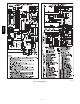
See Fig. 34 and 35 for thermostat connections.
NOTE: The air conditioning relay disable jumper ACRDJ must
be disconnected to allow thermostat control of the outdoor unit
staging. (See Fig. 34.)
The thermostat closes the R to G-and-Y1 circuits for low cooling
or closes the R to G-and-Y1-and-Y2 circuits for high cooling. The
R to Y1 circuit starts the outdoor unit on low cooling speed, and
the R to G-and-Y1 circuit starts the furnace blower motor BLWM
at low-cooling airflow which is the true on-board CF selection as
shown in Fig. 54. The R to Y1-and-Y2 circuits start the outdoor
unit on high-cooling speed, and the R to G-and-Y/Y2 circuits start
the furnace blower motor BLWM at high-cooling airflow.
High-cooling airflow is based on the A/C selection shown in Fig.
54.
The electronic air cleaner terminal EAC-1 is energized with 115
vac whenever the blower motor BLWM is operating.
When the thermostat is satisfied, the R to G-and-Y1 or R to
G-and-Y1-and-Y2 circuits are opened. The outdoor unit stops, and
the furnace blower BLWM and electronic air cleaner terminal
EAC-1 will remain energized for an additional 90 seconds. Jumper
Y1 to DHUM to reduce the cooling off-delay to 5 seconds. (See
Fig. 54.)
4. Dehumidification Mode
See Fig. 34 and 35 for thermostat connections.
The dehumidification output, D or DHUM on the Thermostat
should be connected to the furnace control thermostat terminal
DHUM. When there is a dehumidify demand, the DHUM input is
activated, which means 2 4 vac signal is removed from the DHUM
input terminal. In other words, the DHUM input logic is reversed.
The DHUM input is turned ON when no dehumidify demand
exists. Once 24 vac is detected by the furnace control,
dehumidification capability is activated. If the DHUM input is
removed for more than 48 hours, the furnace control reverts back
to non-dehumidification mode.
The cooling operation described above in the Cooling Mode
section also applies to operation with a dehumidification
thermostat. The exceptions are listed below:
a. Low cooling – When the R to G-and-Y1 circuit is closed
and there is a demand for dehumidification, the furnace
blower motor BLWM will drop the blower airflow to 86%
of low cooling airflow which is the true on-board CF
selectionasshowninFig.54.
b. High cooling – When theR to G-and Y/Y2circuit isclosed
and there is a demand for dehumidification, the furnace
blower motor BLWM will drop the blower airflow to 86%
of high-cooling airflow. High-cooling airflow is based on
the A/C selection shown in Fig. 54.
c. Cooling off-delay – When the “call for cooling” is
satisfied and there is a demand for dehumidification, the
cooling blower-off delay is decreased from 90 seconds
to 5 seconds.
Super Dehumidify Mode
Super-Dehumidify mode can only be entered if the furnace control
is in the Thermidistat mode and there is a demand for
dehumidification. The cooling operation described in Cooling
Mode section above also applies to operation with a Thermidistat.
The exceptions are listed below:
1. Low cooling –WhentheRtoY1circuitisclosed,RtoG
circuit is open, and there is a demand for dehumidification,
the furnace blower motor BLWM will drop the blower air-
flow to 65% of low-cooling airflow for a maximum of 10
minutes each cooling cycle or until the R to G circuit closes
or the demand for dehumidification is satisfied. Low-cool-
ing airflow is the true on-board CF selection as shown in
Fig. 54.
2. High cooling – When the R to Y/Y2 circuit is closed, R to
G circuit is open, and there is a demand for dehumidifica-
tion, the furnace blower motor BLWM will drop the blower
airflow to 65% of high-cooling airflow for a maximum of
10 minutes each cooling cycle or until the R to G circuit
closes or the demand for dehumidification is satisfied.
High-cooling airflow is based on the A/C selection shown
in Fig. 54.
3. Cooling off-delay – When the “call for cooling” is satisfied
and there is a demand for dehumidification, the cooling
blower-off delay is decreased from 90 seconds to 5
seconds.
Continuous Blower Mode
When the R to G circuit is closed by the thermostat, the blower
motor BLWM will operate at continuous blower airflow.
Continuous blower airflow selection is initially based on the CF
selection shown in Fig. 54. Factory default is shown in Fig. 54.
Terminal EAC-1 is energized as long as the blower motor BLWM
is energized.
During a call for heat, the furnace control CPU will transition the
blower motor BLWM to continuous blower airflow, minimum-heat
airflow, or the mid-range airflow, whichever is lowest. The blower
motor BLWM will remain ON until the main burners ignite then
shut OFF and remain OFF for the blower-ON delay (45 seconds in
intermediate heat, and 25 seconds in maximum-heat), allowing the
furnace heat exchangers to heat up more quickly, then restarts at
the end of the blower-ON delay period at modulating or
maximum-heat airflow respectively.
The blower motor BLWM will revert to continuous-blower
airflow after the heating cycle is completed. When the thermostat
satisfies, the furnace control CPU will drop the blower motor
BLWM to minimum-heat airflow during the selected blower-OFF
delay period before transitioning to continuous-blower airflow.
When the thermostat “calls for low-cooling”, the blower motor
BLWM will operate at low-cooling airflow. When the thermostat is
satisfied, the blower motor BLWM will operate an additional 90
seconds at low-cooling airflow before transitioning back to
continuous-blower airflow.
When the thermostat “calls for high-cooling”, the blower motor
BLWM will operate at high cooling airflow. When the thermostat
is satisfied, the blower motor BLWM will operate an additional 90
seconds at high-cooling airflow before transitioning back to
continuous-blower airflow.
When the R to G circuit is opened, the blower motor BLWM will
continue operating for an additional 5 seconds, if no other function
requires blower motor BLWM operation.
Continuous Blower Speed Selection from Thermostat
To select different continuous-blower airflows from the room
thermostat, momentarily turn off the FAN switch or push button on
the room thermostat for 1-3 seconds after the blower motor
BLWM is operating.
The fu rnace co n t ro l CPU w i ll shi ft th e continuous-blower airflow
from the factory setting to the next highest CF selection airflow as
shown in Fig. 54. Momentarily turning off the FAN switch again at
the thermostat will shift the continuous-blower airflow up one
more increment. If you repeat this procedure enough you will
eventually shift the continuous blower airflow to the lowest CF
selection as shown in Fig. 54. The selection can be changed as
many times as desired and is stored in the memory to be
auto m atically u sed fo llo w ing a po w er interruption.
987MA