
Instruction manual


59
To adjust manifold pressure to obtain input rate for Maximum
Heat:
1. Make sure the gas supply is turned off to the furnace and at
the electric switch on the gas valve.
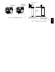
2. Remove the 1/8 inch NPT plug from the outlet pressure tap
on the gas valve.
3. Connect a manometer to the outlet pressure tap on gas
valve.
4. Turn on furnace power supply.
5. Turn gas supply manual shutoff valve to ON position.
6. Turn furnace gas valve switch to ON position.
7. Jumper the R to W/W1 and W2 thermostat connections at
the furnace control board.
8. After the main burners ignite and the blower starts, confirm
Maximum Heat manifold pressure is correct, based on the
manifold pressure tables in the installation instructions.
9. To adjust the Maximum Heat manifold pressure, slowly turn
adjusting screw counterclockwise (out) to decrease
manifold pressure or clockwise (in) to increase manifold
pressure. Turn adjustment no more than one click per
second until you obtain the required manifold pressure.
10. Main burner flame should be clear blue, almost transparent.
11. After adjusting the Maximum Heat manifold pressure,
remove jumpers across thermostat connections to terminate
the call for heat.
12. Wait for blower off-delay to finish then reset 115-v power to
furnace.
To adjust manifold pressure to obtain input rate for Minimum Heat:
1. TurnSW1--2ONandSW4--2mustbeOFF.
2. Jumper R and W/W1 thermostat connections on control to
start furnace.
3. After the main burners ignite and the blower starts, confirm
Minimum Heat manifold pressure is correct, based on the
manifold pressure tables in the installation instructions.
4. To adjust the Maximum Heat manifold pressure, slowly turn
adjusting screw counterclockwise (out) to decrease
manifold pressure or clockwise (in) to increase manifold
pressure. Turn adjustment no more than one click per
second until you obtain the required manifold pressure.
5. After adjusting the manifold pressure, remove jumpers
across thermostat connections to terminate the call for heat.
Wait until the blower off delay is completed.
6. Move setup switch SW1-2 to the OFF position.
7. Turn gas supply manual shutoff valve to OFF position.
8. Turn off furnace power supply.
9. Remove manometer from the inlet pressure tap of the gas
valve.
10. Apply pipe dope sparingly to end of inlet gas pipe plug and
re-install in the gas valve.
11. Re-install cap over adjustment screw on the top of the gas
valve.
FURNACE OVERHEAT ING HAZARD
Failure to follow this caution may result in shortened
furnace life.
Set air temperature rise within limits specified on the rating
plate to prevent reduced life of furnace components.
Operation is within a few degrees of the mid--point of rise
rangewhensetupswitchSW1--4isOFF.
CAUTION
!
FURNACE DAMAGE HAZARD
Failure to follow this caution may result in overheating the
heat exchangers or condensing flue gases in heat exchanger
areas not designed for condensate.
Temperature rise must be within limits specified on unit
rating plate. Operation is within a few degrees of midpoint
ofriserangewhensetupswitchSW1--4isOFF.
CAUTION
!
Adjust Temperature Rise
When setup switch SW1-4 is ON, operation will be near the high
end of the rise range for improved comfort.
Furnace must operate within ranges of temperature rise specified
on the furnace rating plate. Determine air temperature rise as
follows:
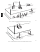
1. Place thermometers in return and supply ducts as near
furnace as possible. Be sure thermometers do not see heat
exchanger so that radiant heat does not affect readings. This
practice is particularly important with straight-run ducts.
2. When thermometer readings stabilize, subtract return-air
temperature from supply-air temperature to determine air
temperature rise.
NOTE: Temperature rise can be determined for Minimum Heat,
Intermediate Heat and Maximum Heat operation by locking the
furnace in each mode of operation. The mode of operation is based
on the position of Set-up switch SW1-2 and SW4-2 on the furnace
control board.
The furnace is capable of automatically providing proper airflow to
maintain the temperature rise within the range specified on furnace
rating plate. If temperature rise is outside this range, proceed as
follows:
a. Check gas input for minimum, intermediate and maximum
heat operation.
b. Check derate for altitude if applicable.
c. Check all return and supply ducts for excessive restrictions
causing static pressure greater than 0.5-in. w.c.
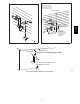
d. Ensure Low Heat Rise Adjust switch SW1--3 on furnace
control is in ON position when a bypass humidifier is used.
(See Fig. 54 for switch location.)
e. Check Troubleshooting Guide for Variable--Speed Step
Modulating Condensing Furnaces.
To lock the furnace in Minimum Heat:
1. Turn SW1 --2 ON at the furnace control. Set up switch
SW4--2 must be OFF.
2. Connect a jumper across R and W/W1 at the thermostat
terminals at the furnace control.
3. Allow the burners to ignite and the blower to turn on.
4. Allow the supply temperature to stabilize and verify the
proper rise range.
If the temperature rise is too high or too low in Minimum Heat:
1. Remove jumpers from R and W/W1.
2. Wait until the blower off delay is completed.
3. Turn 115 VAC power off.
4. Check the position of Set up switch SW1--3. When set to
ON, airflow is raised 18% for Minimum Heat and for
Intermediate Heat. Factory default position is OFF.
5. Turn 115 VAC power on.
6. Re--check Minimum Heat T emperature Rise
987MA