
Instruction manual


58
FIRE OR EXPLOSION HAZARD
Failure to follow this warning could result in personal
injury, death, and/or property damage.
Never purge a gas line into a combustion chamber. Never
test for gas leaks with an open flame. Use a commercially
available soap solution made specifically for the detection
of leaks to check all connections. A fire or explosion may
result causing property damage, personal injury or loss of
life.
!
WARNING
Adjustments
FIRE HAZARD
Failure to follow this warning could result in personal
injury, death and/or property damage.
DO NOT bottom out gas valve regulator adjusting screw.
This can result in unregulated manifold pressure and result
in excess overfire and heat exchanger failures.
!
WARNING
FURNACE DAMAGE HAZARD
Failure to follow this caution may result in reduced furnace
life.
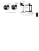
DO NOT redrill orifices. Improper drilling (burrs,
out-- of--round holes, etc.) can cause excessive burner noise
and misdirection of burner flames. This can result in flame
impingement of heat exchangers, causing failures. (See Fig.
51.)
CAUTION
!
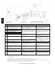
For proper operation and long term reliability , the Furnace input
rate must be within +2 percent of input rate on furnace rating plate.
The gas input rate on rating plate is for installations at altitudes up
to 2000 ft. (609.6M).
In the USA., the input rating for altitudes above 2000 ft. (609.6M)
must be reduced by 2 percent for each 1000 ft. (304.8M) above sea
level. Refer to Table 16.
In Canada, the input rating must be derated by 5 percent for
altitudes of 2000 ft. (609.6M) to 4500 ft. (1371.6M) above sea
level.
To adjust manifold pressure to obtain the proper input rate, first,
determine if the furnace has the correct orifice installed. At higher
altitudes or different gas heat contents, it may be necessary to
change the factory orifice to a different orifice. Tables have been
provided in the furnace installation instructions to match the
required orifice to the manifold pressure to the heat content and
specific gravity of the gas. To do this:
a. Obtain average heat value (at installed altitude) from local
gas supplier.
b. Obtain average specific gravity from local gas supplier.
c. Find installation altitude range for your installation in the
manifold pressure tables. See Table 19.
d. Find closest natural gas heat value and specific gravity in
Table 19.
e. Follow heat value and specific gravity lines to point of
intersection to find orifice size and maximum and minimum
manifold pressure settings for proper operation.
f. Check and verify burner orifice size in furnace. Never
assume orifice size. Always check and verify.
NOTE: For Canadian altitudes of 2000 to 4500 ft. (609.6 to
1371.6M), use USA altitudes of 2001 to 3000 ft. (609.6 to
914.4M).
NOTE: If orifice hole appears damaged or it is suspected to have
been redrilled, check orifice hole with a numbered drill bit of
correct size. Never redrill an orifice. A burr--free and squarely
aligned orifice hole is essential for proper flame characteristics.
See Example 1.
g. Replace original orifice with correct size, if required by
Table 19. Use only factory-- supplied orifices. See
EXAMPLE 1.
EXAMPLE 1
EXAMPLE: 0 -- 2000 ft. (0 -- 609.6M) altitude
Heating value = 1050 Btu/cu ft.
Specific gravity = 0.62
Therefore: Orifice No. 44
Manifold pressure: 3.4--in. w.c. for maximum heat, 0.55 --in. w.c.
for minimum heat.
* Furnace is shipped with No. 44 orifices. In this example, all main
burner orifices are the correct size and do not need to be changed to
obtain proper input rate.
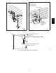
The inlet gas pressure must be checked with the furnace operating
in maximum heat. This is necessary to make sure the inlet gas
pressure does not fall below the minimum pressure of 4.5 in. w.c.
for natural gas. The maximum inlet gas pressure is 13.6 in. of water
column. If the inlet pressure is too low, you will not be able to
adjust the manifold pressure to obtain the proper input rate. To
check the inlet gas pressure:
1. Make sure the gas supply is turned off to the furnace and at
the electric switch on the gas valve.
2. Remove the 1/8 in. NPT plug from the inlet pressure tap on
the gas valve.
3. Connect a manometer to the inlet pressure tap on gas valve.
4. Turn on furnace power supply.
5. Turn gas supply manual shutoff valve to ON position.
6. Turn furnace gas valve switch to ON position.
7. Jumper the R to W/W1 and W2 thermostat connections at
the furnace control board.
8. When main burners ignite, confirm inlet gas pressure is
Between 4.5 in. w.c. and 13.6 in. w.c.
9. Remove jumper across thermostat connections to terminate
call for heat. Wait until the blower off delay is completed.
10. Turn furnace gas valve electric switch to OFF position.
11. Turn gas supply manual shutoff valve to OFF position.
12. Turn off furnace power supply.
13. Remove manometer from the inlet pressure tap of the gas
valve.
14. Apply pipe dope sparingly to end of inlet gas pipe plug and
re--install in the gas valve.
For proper operation and long term reliability, the manifold
pressure must be adjusted within +2 percent of input rate on
furnace rating plate.
The modulating furnace manifold pressure is set at two points. The
first point is Maximum Heat. The second point is Minimum Heat.
Do not adjust Intermediate Heat manifold pressure. Intermediate
Heat manifold pressure is checked as part of the temperature rise,
but is not adjustable. Always adjust Maximum Heat first, then
Minimum Heat.
NOTE: DO NOT set Maximum Heat manifold pressure less than
3.2-- in. w.c. or more than 3.8 in. w.c. for natural gas.
987MA