
Instruction manual

40
(1.2 M) of unobstructed distance to the property line of the
adjacent lot, no type of vent termination is permitted for appliances
with inputs greater than 35,000 btuh.
There are no additional restrictions on unobstructed distances
greater than 8 ft. (2.4 M). All single, two-pipe and concentric vents
may be used, providing all other Code and manufacturer’s
requirements in these instructions are adhered to. Refer to the
appropriate Vent Termination section above for locating the vent
termination
If the unobstructed distance from the foundation to the property
line of the adjacent lot is no less than 4 ft. (1.2 M) and no greater
than 8 ft. (2.4 M), it will be necessary to re-direct the flue gas
plume. In this situation, a concentric vent kit cannot be used. A
2-pipe termination (or single pipe termination when permitted) that
re-directs the flue gas away by use of an elbow or tee, certified to
ULC S636 from the adjacent property line must be used. See Fig.
48.
The concentric vent kit currently cannot be modified to attach an
elbow to the vent portion of the rain cap. A tee attached to the rain
cap could potentially direct the flue gas plume toward the intake air
stream and contaminate the incoming combustion air for the
furnace.
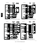
Refer to Fig. 48 for terminations approved for use in Alberta and
Saskatchewan.
Size the Vent and Combustion Air Pipes
General
Furnace combustion air and vent pipe connections are sized for
2-in. (51 mm) pipe. Any pipe diameter change should be made
outside furnace casing in vertical pipe. Any change is diameter to
the pipe must be made as close to the furnace as reasonably
possible.
The Maximum Vent Length for the vent and combustion air pipe
(when used) is determined from the Maximum Equivalent Vent
Length in Table 13 or 15, minus the number of fittings multiplied
by the deduction for each type of fitting used from Table 14.
The measured length of pipe used in a single or 2--pipe termination
is included in the total vent length. Include a deduction for a Tee
when used for Alberta and Saskatchewan terminations. Concentric
vent terminations, pipe lengths or elbows do not require a
deduction from the Maximum Equivalent Vent Length.
1. Measure the individual distance from the furnace to the ter-
mination for each pipe.
2. Select a Maximum Equivalent Vent Length (MEVL) longer
than the measured distance of the individual vent and com-
bustion air connections to the vent termination.
3. Count the number of elbows for each pipe.
4. For each pipe, multiply the number of elbows by the equi-
valent length for the type of elbow used. Record the equi-
valent length of all the elbows for each pipe.
5. If a Tee is used on the termination, record the equivalent
length of the Tee used.
6. Record the equivalent length o f the termination to be used.
7. Subtract the equivalent lengths of the fittings and termina-
tions from the Maximum Equivalent Vent Length.
8. If the Maximum Vent Length calculated is longer than the
individual measured length of the vent pipe and combustion
air pipe, then the diameter of pipe selected may be used.
9. If the Maximum Vent Length calculated is shorter than the
individual measured length of either the vent pipe or the
combustion air pipe, recalculate the Maximum Vent Length
using the next larger diameter pipe.
NOTE: The vent pipe and combustion air pipe must be the same
diameter .
NOTE: If the Maximum Vent Length for diameter of the pipe
selected is longer than the measured length and the equivalent
length of all the fitting and terminations, recalculate using the next
smaller diameter. If the recalculated Maximum Vent Length is
longer than the measured length of the vent pipe and combustion
air pipe, then that diameter of pipe selected may be used.
When installing vent systems of short pipe lengths, use the smallest
allowable pipe diameter . Do not use pipe size greater than required
or incomplete combustion, flame disturbance, or flame sense
lockout may occur.
Combustion Air and Vent Piping Insu lation
Guidelines
NOTE: Use closed cell, neoprene insulation or equivalent.
The vent pipe may pass through unconditioned areas. The amount
of exposed pipe allowed is shown in Table 12.
1. Using winter design temperature (used in load calculations),
find appropriate temperature for your application and fur-
nace model.
2. Determine the amount of total and exposed vent pipe.
3. Determine required insulation thickness for exposed pipe
length(s).
4. When combustion air inlet piping is installed above a sus-
pended ceiling, the pipe MU ST be insulated with moisture
resistant insulation such as Armaflex or other equivalent
type of insulation.
5. Insulate combustion air inlet piping when run in warm, hu-
mid spaces.
6. Install the insulation per the insulation manufacturer’s in-
stallation instructions.
NOTE: Pipe length (ft. / M) specified for maximum pipe lengths
located in unconditioned spaces cannot exceed total allowable pipe
length as calculated from Table 13 or 15.
Configure the Furnace
CARBON MONOXIDE POISONING HAZARD
Failure to follow this warning could result in personal
injury or death.
To route the vent pipe and combustion air pipe through the
furnace, the manufacturer supplied kit must be used. Failure
to properly seal the blower compartment from the furnace
vestibule could result in the circulation of carbon monoxide
throughout the structure. The vent pipe and combustion air
pipe must be a continuous pipe while passing through the
blower compartment. Seals supplied in this kit must be
installed per the instructions provided. Follow all
procedures outlined in these instructions.
WARNING
!
Install the Vent and Combustion Air Pipe
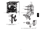
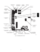
With the furnace installed in the required position, remove the
desired knockouts from the casing. It will be necessary to remove
one knockout for the vent pipe and the other knockout for the
combustion air connection. (See Fig. 11.)
Use a flat blade screwdriver and tap on the knockout on opposite
sides, where the knockout meets the casing. Fold the knockout
down with duct pliers and work the knockout back and forth until
it is removed. Trim any excess metal from the knockout with tin
snips.
The vent elbow can be rotated to the required location on the
casing if necessary. See Fig. 37. T o rotate the vent elbow:
1. Loosen the clamp on the inlet of the vent elbow attached to
the inducer.
987MA