
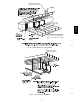
Instruction manual

28
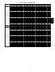
Table 7 -- Air Delivery -- CFM (With Filter) (Continued)
(SW1-5 and SW4-3 set to OFF, except as indicated. See Notes 1 and 2.)
INPUT
BTUH
Cooling Switch Settings External Static Pressure (E.S.P.)
SW2-3 SW2-2 SW2-1 0.1 0.2 0.3 0.4 0.5 0.6 0.7 0.8 0.9 1.0
100000
OFF OFF OFF 1815 1810 1805 1800 1785 1765 1745 1720 1710 1685
OFF OFF ON 765 775 755 730 710
OFF ON OFF 930 940 935 930 935
OFF ON ON 1095 1120 1120 1105 1095 1100 1085 1075 1055 1050
ON OFF OFF 1245 1270 1275 1280 1290 1280 1285 1270 1260 1245
ON OFF ON 1440 1445 1455 1445 1450 1440 1440 1425 1415 1405
ON ON OFF 1815 1810 1805 1800 1785 1765 1745 1720 1710 1685
ON ON ON 1815 1810 1805 1800 1785 1765 1745 1720 1710 1685
Maximum Cooling Airflow
2
2055 2055 2050 2045 2030 2015 1995 1940 1870 1805
Maximum Heat Airflow
3
1495 1515 1515 1520 1525 1520 1515 1505 1490 1480
Intermediate Heat Airflow
3
900 905 900 900 890
Minimum Heat Airflow
3
725 725 720 690 670
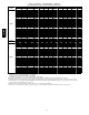
INPUT
BTUH
Cooling Switch Settings External Static Pressure (E.S.P.)
SW2-3 SW2-2 SW2-1 0.1 0.2 0.3 0.4 0.5 0.6 0.7 0.8 0.9 1.0
120000
6
OFF OFF OFF 1850 1855 1860 1855 1850 1830 1805 1775 1750 1730
OFF OFF ON 765 745 740 705 680
OFF ON OFF 930 925 915 900 885
OFF ON ON 1095 1100 1110 1105 1085
ON OFF OFF 1265 1255 1265 1280 1275 1285 1270 1260 1250 1230
ON OFF ON 1465 1455 1470 1465 1465 1470 1455 1450 1435 1415
ON ON OFF 1850 1855 1860 1855 1850 1830 1805 1775 1750 1730
ON ON ON 2200 2200 2200 2190 2185 2170 2145 2085 1990 1890
Maximum Cooling Airflow
2
2200 2200 2200 2190 2185 2170 2145 2085 1990 1890
Maximum Heat Airflow
3
1815 1820 1825 1820 1815 1795 1775 1745 1720 1700
Intermediate Heat Airflow
3
1095 1100 1110 1105 1085
Minimum Heat Airflow
3
905 900 890 875 855
1. Nominal 350 CFM/ton cooling airflow is delivered with SW1-5 and SW4-2 set to OFF.
Set SW1-5 to ON for nominal 400 CFM/ton (+15% airflow).
Set SW4-3 to ON for nominal 325 CFM/ton (-7% airflow).
Set both SW1-5 and SW4-3 to ON for nominal 370 CFM/ton (+7% airflow).
2. Maximum cooling airflow is achieved when switches SW3-1, SW3-2, SW3-3 and SW1-5 are set to ON, and SW4-3 is set to OFF.
3. All heating CFM's are when low/medium heat rise adjustment switch (SW1-3) and comfort/efficiency adjustment switch (SW1-4) are both set to OFF.
4. Ductwork must be sized for high-heating CFM within the operational range of E.S.P. Operation within the blank areas of the chart is not recommended
because high-heat operation will be above 1.0 E.S.P.
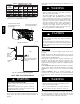
5. All airflows on 21" (533 mm) casing size furnaces are 5% less on side return only installations.)
6. Side returns for 24.5" (622 mm) casing sizes require two sides, or side and bottom, to allow sufficient airflow at the return of the furnace.
987MA