
Instruction manual

17
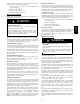
CUT HAZARD
Failure to follow this caution may result in personal injury.
Sheet metal parts may have sharp edges or burrs. Use care
and wear appropriate protective clothing, safety glasses and
gloves when handling parts, and servicing furnaces.
CAUTION
!
A11305
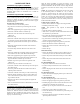
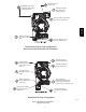
Fig. 11 -- Knockout Removal
OPEN STAND
PIPE FOR
A/C OR
HUMIDIFIER
DRAIN
TEE
TO OPEN
DRAIN
A11276
Fig. 12 -- Example of Field Drain Attachment
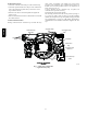
INSTALL CLAMPS ON DRAIN TUBE
ATTACH DRAIN TUBE TO CONDENSATE
DRAIN TRAP
PULL DRAIN STUB
THROUGH CASING
A11342
Fig. 13 -- Formed Tube Grommet
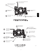
RIGHT SIDE DRAIN ELBOW
Cut and remove formed end of
drain tube for left side and horizontal
drain connection
A11388
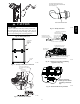
Fig. 14 -- Modify Drain Tube
LEFT SIDE DRAIN ROUTED BEHIND INDUCER
TRAP, DRAIN ELBOW WITH DISCHARGE PIPE
Attach tube to condensate trap
Cut formed end o
condensate drain tube
Connect short end
of “Z” pipe to modied
drain tube
Field supplied 1/2” CPVC
coupling & drain extension
17 1/2“, 21” and 24 1/2” casing
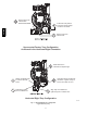
Field supplied 1/2”
CPVC to drain
Casing grommet from
loose parts bag
Modied drain tube connect to
condensate trap and “Z” pipe
Field-supplied 1/2” CPVC coupling & drain
pipe 17 1/2“, 21” and 24 1/2” casings
A11344
Fig. 15 -- Drain Trap Connection and Routing
(Appearance May Vary)
Remove knockout.
Install grommet before
relocating condensate
trap.
A11348
Fig. 16 -- Horizontal Drain Trap Grommet
987MA