
Instruction manual

16
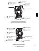
CONDENSATE DRAIN CONNECTION
Upflow/Downflow Orientation
In the Upflow or Downflow orientation, the condensate trap is
inside the furnace casing. The condensate drain must be routed
from the trap through the furnace casing. The condensate drain can
be routed through the left or right side of the casing. (The left or
right side is as you are viewing the furnace.) The furnace
condensate drain can be connected to the Air Conditioning
condensate drain as shown in Fig. 12.
NOTE: On narrower casings, it may be easier to remove the
condensate trap, connect the drain line components and re-install
the condensate trap. Read the steps thoroughly to familiarize
yourself with the required steps.
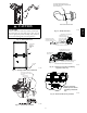
For Right Side Condensate Drain:
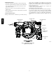
1. Remove the 7/8 --in. knock-- out from the right side of the
casing. (See Fig. 11 .)
2. Remove the pre--formed drain tube and two spring clamps
from the loose parts bag.
3. Slide a spring clamp 1 inch (25 mm) down the plain end of
the drain tube.
4. From inside the casing, insert the formed grommet end of
the tube through the 7/8--in. knockout in the casing.
5. Pull the tube through the casing from the outside until it is
seated in the knockout
6. Attach the plain end of the drain tube to the outlet stub on
the drain trap. Secure the drain tube to the trap with the
spring clamp.
7. Slide a spring clamp over the open end of the drain tube
outside the casing.
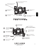
8. Open the spring clamp and connect a field--supplied 1/2--in.
CPVC street elbow to the open end of the drain tube. (See
Fig. 13.)
9. Connect additional 1/2 --in. CPVC piping to a condensate
pump approved for use with acidic furnace condensate or to
a code--approved drain.
For Left Side Condensate Drain Connection:
1. For left side condensate drain age, the drain line is routed
from the condensate trap, behind the inducer and out
through the left side of the casing. A pre-formed “Z” pipe is
provided in the loose parts bag shipped with the furnace.
The “Z” pipe is long enough to extend out of the casing on
the 14 3/16-in. (360 mm) wide furnace. Larger casings will
require a field supplied CPVC pipe and to extend the drain
line out of the furnace.
2. The “Z” pipe is connected to the condensate trap by
modifying the formed rubber drain tube. Connect the drain
line as shown below:
3. Remove the knock-out from the left side of the casing. (See
Fig. 11.)
4. Install the grommet for the 1/2-in. CPVC drain line in the
7/8-in. knockout in the casing.
5. Remove the pre-formed drain tube, the offset 1/2-in. CPVC
pipe and two spring clamps from the loose parts bag.
6. Remove the formed grommet on the tube by cutting the
tube along the vertical line located about 1 inch (25 mm)
away from the formed grommet.(See Fig. 14.)
7. Slide a spring clamp 1 inch (25 mm) down the plain end of
the drain tube.
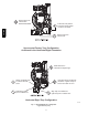
8. With the bend in the tube oriented horizontally and plain
end of the tube pointing away from you, insert the 1/2-in.
CPVC pipe into the other end of the drain tube. Rotate the
tube so the offset in the tube points away from you. Slide a
spring clamp over the open end of the 1/2-in. CPVC tube
and secure the cut end of drain tube to the pipe. (See Fig.
15)
9. Prime the bare end of the pipe with CPVC primer.
10. Route the offset pipe behind the inducer assembly and
through the grommet in the casing, if the “Z” pipe is long
enough. If the “Z” pipe is not long enough, continue with
installation.
11. Attach the plain end of the drain tube to the outlet stub on
the drain trap. Secure the drain tube to the trap with the
spring clamp.
12. If the “Z” pipe does not extend through the casing, slide a
piece of field supplied CPVC through the grommet in the
casing, otherwise, go to Step 17.
13. Cement a 1/2-in. CPVC coupling to the end of the CPVC
pipe.
14. Apply cement to the end of the “Z” pipe connected to the
condensate trap.
15. Connect the field-supplied CPVC pipe to the CPVC pipe
connected to the condensate trap.
16. Cut off excess CPVC pipe outside the casing.
17. Connect additional 1/2-in. CPVC piping to a condensate
pump approved for use with acidic furnace condensate or to
a code-approved drain.
18. When a condensate pump is not used, slope the pipe away
from the furnace to allow for proper drainage.
Horizontal Orientation
1. In the Horizontal orientation, a field supplied accessory
drain trap grommet is required to seal the gap between the
casing and the condensate trap for direct vent applications,
only. The condensate trap outlet extends 2 in. (51 mm)
below the furnace casing. To allow for servicing the trap,
the condensate drain tube in the loose parts bag can be
modified to make a coupler to allow for future service of the
condensate trap and drain line.
2. Remove the knock-out for the condensate trap in the side of
the casing.
3. Install the drain trap grommet in the casing. (For direct vent
applications.) If necessary, remove the trap, install the
grommet and re-install the trap.
4. Remove the pre-formed drain tube, the offset 1/2-in. CPVC
pipe and two spring clamps from the loose parts bag.
5. Remove the formed grommet on the tube to create an elbow
or straight connector. (See Fig. 14.)
6. Connect the cut tube to the outlet of the condensate trap
with 1 spring clamp.
7. Slide the other spring clamp down the plain end of the drain
tube.
8. Connect additional 1/2-in. CPVC piping to the open end of
the tube.
9. Slide the spring clamp down over the 1/2-in. CPVC pipe
10. Connect additional 1/2-in. CPVC piping to a condensate
pump approved for use with acidic furnace condensate or to
a code-approved drain.
11. When a condensate pump is not used, slope the pipe away
from the furnace to allow for proper drainage.
987MA