987MA MODULATING 4--WAY MULTIPOISE GAS FURNACE SERIES A . Installation, Start--up, Operating and Service and Maintenance Instructions NOTE: Read the entire instruction manual before starting the installation. Checklist . . . . . . . . . . . . . . . . . . . . . . . . . . . . . . . . . . . . . . . . 61 SAFETY CONSIDERATIONS . . . . . . . . . . . . . . . . . . . . . . . . . 3 SERVICE AND MAINTENANCE PROCEDURES . . . . . . . . 67 Cleaning Heat Exchangers . . . . . . . . . . . . . . . . . . . . . . . . . . .
Required Notice for Massachusetts Installations 987MA IMPORTANT The Commonwealth of Massachusetts requires compliance with regulation 248 CMR as follows: 5.08: Modifications to NFPA--54, Chapter 10 2) Revise 10.8.3 by adding the following additional requirements: a.
! WARNING FIRE, EXPLOSION, ELECTRICAL SHOCK, AND CARBON MONOXIDE POISONING HAZARD Failure to follow this warning could result in dangerous operation, personal injury, death, or property damage. Improper installation, adjustment, alteration, service, maintenance, or use can cause carbon monoxide poisoning, explosion, fire, electrical shock, or other conditions which may cause personal injury or property damage.
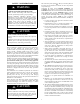
987MA INTRODUCTION This 4--way multipoise Category IV condensing furnace is CSA design--certified as a direct (2-pipe) or non-direct vent (1-pipe) furnace. (See Fig. 2.)The furnace is factory--shipped for use with natural gas. The furnace can be converted in the field for use with propane gas when a factory-supplied conversion kit is used. Refer to the furnace rating plate for conversion kit information. This furnace is not approved for installation in mobile homes, recreational vehicles, or outdoors.
ACCESSORIES See Product Data Sheet for a list of accessories for this product LOCATION ! CAUTION wood flooring (refer to SAFETY CONSIDERATIONS). S be located close to the chimney or vent and attached to an air distribution system. Refer to Air Ducts section. S be provided ample space for servicing and cleaning. Always comply with minimum fire protection clearances shown in Table 2 or on the furnace clearance to combustible construction label.
! WARNING ! WARNING FIRE, INJURY OR DEATH HAZARD FIRE HAZARD Failure to follow this warning could result in personal injury, death and/or property damage. Failure to follow this warning could result in personal injury, death and/or property damage. When the furnace is installed in a residential garage, the burners and ignition sources must be located at least 18 in. (457 mm) above the floor. The furnace must be located or protected to avoid damage by vehicles.
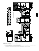
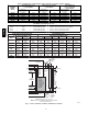
987MA 987MA A11449 Fig. 1 -- Dimensional Drawing NOTE: Doors may vary by model. a. For 800 CFM--- 16--- in. (406 mm) round or 14 1/2 x 12--- in. (368 x 305 mm) rectangle. b. For 1200 CFM--- 20--- in. (508 mm) round or 14 1/2 x 19 1/2--- in. (368 x 495 mm) rectangle. c. For 1600 CFM--- 22--- in. (559 mm) round or 14 1/2 x 22 1/16--- in. (368 x 560mm) rectangle. d. For airflow requirements above 1800 CFM, see Air Delivery table in these installation instructions for specific use of single side inlets.
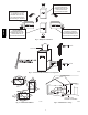
THE BLOWER IS LOCATED BELOW THE BURNER SECTION, AND CONDITIONED AIR IS DISCHARGED UPWARD. 987MA THE BLOWER IS LOCATED TO THE RIGHT OF THE BURNER SECTION, AND AIR CONDITIONED AIR IS DISCHARGED TO THE LEFT. THE BLOWER IS LOCATED TO THE LEFT OF THE BURNER SECTION, AND CONDITIONED AIR IS DISCHARGED TO THE RIGHT. THE BLOWER IS LOCATED ABOVE THE BURNER SECTION, AND CONDITIONED AIR IS DISCHARGED DOWNWARD A02097 Fig. 2 -- Multipoise Orientations 80 / 27˚C 60 / 16˚C SUPPLY AIR A10490 Fig.
Introduction Direct Vent (2-- pipe) Applications When the furnace is installed as a direct vent (2-pipe) furnace, no special provisions for air for combustion are required. However, other gas appliances installed in the space with the furnace may require outside air for combustion. Follow the guidelines below to insure that other gas appliances have sufficient air for combustion.
Table 3 – Minimum Free Area Required for Each Combustion Air Opening or Duct to Outdoors TWO HORIZONTAL DUCTS (1 SQ. IN./2,000 BTUH) (1,100 SQ. MM/KW) FURNACE INPUT (BTUH) SINGLE DUCT OR OPENING (1 SQ. IN./3,000 BTUH) (734 SQ. MM/KW) Free Area of Opening and Duct Sq. In (Sq. mm) Round Duct In. (mm) Dia 20 (12904) 30 (19355) TWO OPENINGS OR VERTICAL DUCTS (1 SQ. IN./4,000 BTUH) (550 SQ. MM/KW) Free Area of OpenRound Duct ing and Duct In. (mm) Dia. Sq. In (mm) Free Area of Opening and Duct Sq. In (Sq.
Condensate Trap--Upflow Orientation When the furnace is installed in the upflow position, it is not necessary to relocate the condensate trap or associated tubing. Refer to Fig. 7 for upflow condensate trap information. Refer to Condensate Drain section for information how to install the condensate drain. Condensate Trap--Downflow Orientation. When the furnace is installed in the downflow position, the factory--installed trap will be located at the upper left corner of the collector box.
For Horizontal Left only: S Connect the relief tube to the relief port of the condensate trap. S Connect the pressure switch tube to the port on the collector box next to the condensate trap. Trim off any excess tube to avoid sags or kinks in the tube. S Rotate the vent elbow to the desired position and tighten the clamp 15 lb--in. S Refer to Condensate Drain section for information how to install the condensate drain.
Remove pressure switch tube from pressure switch port. Remove relief tube from relief port on condensate trap. Remove tube from relief port. 987MA Remove trap from collector box. Loosen clamp on inlet to vent elbow. Remove middle and bottom plugs. DO NOT DISCARD. 7 Route tube through inducer stand-offs 8 Install plugs on open ports on collector box. Attach condensate trap with screw to collector box. Connect relief tube to port on collector box. 9 Trim excess tube.
Remove plug from collector box. DO NOT DISCARD. 987MA If alternate vent position is required, loosen clamp on inlet of vent elbow. Remove trap from collector box. Unconverted Factory Trap Configuration As Viewed in the Horizontal Right Orientation Slide relief tube in stand-offs to adjust length. Attach condensate trap to collector box with screw. Vent elbow shown in alternate orientation. Tighten clamp on inlet to vent elbow 15 lb.-in. Install plug in open port on collector box.
Remove trap from collector box. If alternate vent position is required, loosen clamp on vent elbow inlet. Remove relief tube from relief port on condensate trap. 987MA Remove pressure switch tube from port on collector box. Remove relief tube from port on collector box. Remove middle and right plug from collector box. Unconverted Factory Trap Configuration As Viewed in the Horizontal Left Orientation Install plugs in open ports on collector box.
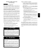
CONDENSATE DRAIN CONNECTION Upflow/Downflow Orientation 9. 10. In the Upflow or Downflow orientation, the condensate trap is inside the furnace casing. The condensate drain must be routed from the trap through the furnace casing. The condensate drain can be routed through the left or right side of the casing. (The left or right side is as you are viewing the furnace.) The furnace condensate drain can be connected to the Air Conditioning condensate drain as shown in Fig. 12.
Cut and remove formed end of drain tube for left side and horizontal drain connection CUT HAZARD A11388 Fig. 14 -- Modify Drain Tube Failure to follow this caution may result in personal injury. Sheet metal parts may have sharp edges or burrs. Use care and wear appropriate protective clothing, safety glasses and gloves when handling parts, and servicing furnaces. A11305 Fig.
INSTALLATION 3. Install another nut on other side of furnace base. (Install flat washer if desired.) 4. Adjust outside nut to provide desired height, and tighten inside nut to secure arrangement. 5. Reinstall bottom closure panel if removed. Upflow Installation NOTE: The furnace must be pitched forward as shown in Fig. 22 for proper condensate drainage. 987MA Supply Air Connections For a furnace not equipped with a cooling coil, the outlet duct shall be provided with a removable access panel.
Horizontal Installation NOTE: The furnace must be pitched forward as shown in Fig. 22 for proper condensate drainage. ! WARNING FIRE, EXPLOSION, AND CARBON MONOXIDE POISONING HAZARD Failure to follow this warning could result in personal injury, death, or property damage. Do not install the furnace on its back or hang furnace with control compartment facing downward. Safety control operation will be adversely affected. Never connect return--air ducts to the back of the furnace.
Table 5 – Filter Size Information -- In. (mm) FURNACE CASING WIDTH 17---1/2 (445) 21 (533) 24---1/2 (622) SIDE RETURN 16 x 25 x 3/4 (406 x 635 x 19) 16 x 25 x 3/4 (406 x 635 x 19) 16 x 25 x 3/4 (406 x 635 x 19) FILTER SIZE BOTTOM RETURN 16 x 25 x 3/4 (406 x 635 x 19) 20 x 25 x 3/4 (508 x 635 x 19) 24 x 25 x 3/4 (610 x 635 x 19) FILTER TYPE Washable* Washable* Washable* * Recommended to maintain air filter face velocity. See Product Data for part number.
-in. Furnace 14-3/16 and 17-1/2-in. Furnace 4-in. Block Off Plate 4-Ton or less, AC capacity airflow 1/2-in. 987MA Screws 20-in. Media Cabinet 16-in. Media Cabinet Media Cabinet Installation Side Return Media Cabinet Installation Option for 4-Ton or Less A/C Capacity 21- or 24-1/2-in. Furnace 21-in. Furnace up to 5-Ton AC Capacity Up to 5-Ton AC capacity airflow 24-1/2-in. Furnace up to 4-Ton AC Capacity 20- or 24-in. Media Cabinet 45° Bottom Return Plenum Transition 20- or 24-in.
FURNACE (OR COIL CASING WHEN USED) FURNACE APPROVED COIL ASSEMBLY OR COIL BOX COMBUSTIBLE FLOORING COMBUSTIBLE FLOORING A PLENUM OPENING D B DOWNFLOW SUBBASE FLOOR OPENING C 987MA SHEET METAL PLENUM SHEET METAL PLENUM FLOOR OPENING FLOOR OPENING A10491 Fig. 18 -- Installation on Combustible Flooring Table 6 – Opening Dimensions -- In. (mm) FURNACE CASING WIDTH IN.
UPFLOW HORIZONTAL 90° 90° YES YES YES 120° MIN YES 120° MIN YES YES 120° MIN NO NO NO A10493 Fig. 19 -- Duct Flanges 5/ 16″ (8mm) (8mm) 5/ 16″ 1 3/4″ (44mm) 1 3/4″ (44mm) (8mm) 5/16″ BOTTOM CLOSURE PANEL (8mm) 5/ 16″ (44mm) 1 3/ 4″ 3/ (44mm) 1 4″ BOTTOM PLATE A89014 A11092 Fig. 20 -- Leveling Legs Fig. 21 -- Removing Bottom Closure Panel LEVEL 0-IN. (0 MM) TO 1/2-IN. (13 MM) MAX MIN 1/4-IN. (6 MM) TO 1/2-IN. (13 MM) MAX UPFLOW OR DOWNFLOW HORIZONTAL A11237 Fig.
987MA ANY COMBINATION OF 1, 2, OR 3 PERMITTED. A11036 A11037 Fig. 23 -- Upflow Return Air Configurations and Restrictions Fig. 24 -- Downflow Return Air Configurations and Restrictions HORIZONTAL TOP RETURN NOT PERMITTED FOR ANY MODEL A11038 Fig.
COMBUSTION - AIR PIPE (SEE VENTING SECTION) 30 IN. (762 mm) MIN. WORK AREA 987MA 2-IN. (51 mm) ROLLOUT PROTECTION REQUIRED Install 12” x 22” (305 x 559 mm) sheet metal in front of burner compartment area. A11154 Fig. 26 -- Working Platform for Attic Installation COMBUSTION-AIR PIPE (SEE VENTING SECTION) 2-IN. (51 mm) A11155 Fig.
AIR DUCTS 987MA General Requirements The duct system should be designed and sized according to accepted national standards such as those published by: Air Conditioning Contractors Association (ACCA), Sheet Metal and Air Conditioning Contractors National Association (SMACNA) or American Society of Heating, Refrigerating and Air Conditioning Engineers (ASHRAE) or consult The Air Systems Design Guidelines reference tables available from your local distributor.
Table 7 – Air Delivery -- CFM (With Filter) INPUT BTUH 60000 Cooling Switch Settings SW2-3 SW2-2 SW2-1 80000 0.2 0.3 External Static Pressure (E.S.P.) 0.4 0.5 0.6 0.7 OFF OFF OFF 1060 1070 1080 1080 1075 OFF OFF ON 545 530 520 525 510 OFF ON OFF 710 710 710 695 690 OFF ON ON 875 880 890 895 ON OFF OFF 1060 1070 1080 ON OFF ON 1235 1240 ON ON OFF 1235 ON ON ON 0.8 0.9 1.
Table 7 -- Air Delivery -- CFM (With Filter) (Continued) (SW1-5 and SW4-3 set to OFF, except as indicated. See Notes 1 and 2.) INPUT BTUH 987MA 100000 Cooling Switch Settings SW2-3 SW2-2 SW2-1 1200006 0.2 0.3 External Static Pressure (E.S.P.) 0.4 0.5 0.6 0.
GAS PIPING WARNING FIRE OR EXPLOSION HAZARD A failure to follow this warning could result in personal injury, death, and/or property damage. FIRE OR EXPLOSION HAZARD Failure to follow this warning could result in personal injury, death, and/or property damage. If local codes allow the use of a flexible gas appliance connector, always use a new listed connector. Do not use a connector which has previously served another gas appliance.
Table 8 – Maximum Capacity of Pipe NOMINAL IRON PIPE SIZE IN. (MM) 1/2 (13) 3/4 (19) 1 ( 25) 1-1/4 (32) 1-1/2 (39) Field--supplied wiring shall conform with the limitations of 63_F (33_C) rise. LENGTH OF PIPE --- FT (M) 10 (3.0) 20 (6.0) 30 (9.1) 40 (12.1) 50 (15.2) 175 360 680 1400 2100 120 250 465 950 1460 97 200 375 770 1180 82 170 320 660 990 73 151 285 580 900 ! ELECTRICAL SHOCK AND FIRE HAZARD Failure to follow this warning could result in personal injury, death, or property damage.
J--Box Installation WARNING FIRE OR ELECTRICAL SHOCK HAZARD Failure to follow this warning could result in personal injury, death, or property damage. If field--supplied manual disconnect switch is to be mounted on furnace casing side, select a location where a drill or fastener cannot damage electrical or gas components. The J-Box is used when field line voltage electrical connections are made to the furnace wiring harness inside the furnace casing.
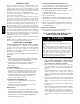
987MA 2. Humidifier (HUM) The HUM terminal is a 24 VAC output, energized when the blower is operating during a call for heat. Connect an accessory 24 VAC, 0.5 amp. maximum humidifier (if used) to the ¼--in. male quick--connect HUM terminal and COM--24V screw terminal on the control board thermostat strip. NOTE: If the humidifier has its own 24 VAC power supply, an isolation relay may be required.
GROUND NEUTRAL LINE VOLTAGE 987MA J BOX LOCATIONS J−BOX MOUNTING SCREWS J−BOX MOUNTING BRACKET GROUND SCREW J−BOX COVER ELECTRIC DISCONNECT SWITCH A11156 COPPER Fig. 30 -- Installing J--Box (When Used) (Appearance May Vary) WIRE ONLY ALUMINUM WIRE A11146 Fig.
To HUM Terminal On To Humidifier Leads Furnace Control Board 24 V Coil To Humidifier Leads To Com/24V Screw Terminal on Thermostat Strip A11157 987MA Fig.
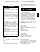
COMMUNICATION CONNECTOR MODEL PLUG CONNECTOR CONTINUOUS FAN (CF) AIRFLOW SETUP SWITCHES OUTDOOR AIR TEMP CONNECTOR SW4 SETUP SWITCHES PL8 - MODULATING GAS VALVE CONNECTOR AIR CONDITIONING (A/C) AIRFLOW SETUP SWITCHES HUMIDIFIER TERMINAL (24-VAC 0.5 AMP MAX.
THERMOSTAT THERMOSTAT D 987MA D 11, and 16 15, and 16 Modulating and 2-Stage Furnace with Single-Speed Heat Pump Modulating and 2-Stage Furnace with Single-Speed Air Conditioner THERMOSTAT THERMOSTAT D D 15, and 16 12 and 16 Modulating and 2-Stage Furnace with Two-Speed Air Conditioner Modulating and 2-Stage Furnace with Two-Speed Heat Pump A11274 Fig.
1. Heat pump MUST have a high pressure switch for dual fuel applications. 2. Refer to outdoor equipment Installation Instructions for additional information and setup procedure. 3. If the heat pump date code is 1501E or earlier, select the “ZONE” position on the two speed heat pump control. Heat pumps with date code 1601E and later do not have or require a “ZONE” selection. 4. Outdoor Air Temperature - sensor must be attached in all dual fuel applications. 5.
VENTING Furnace is set in place in the required orientation. 987MA Special Venting Requirements for Installations in Canada Les autorité es ayant juridiction (inspecteurs de gas, inspecteurs en bâtiments, département des incendies, etc) devraient être consultées avant l’installation afin de déterminer si un permis est requis. ! Installation in Canada must conform to the requirements of CAN/CSA B149 code. Vent systems must be composed of pipe, fittings, cements, and primers listed to ULC S636.
Materials U.S.A. Combustion air and vent pipe, fittings, primers, and solvents must conform to American National Standards Institute (ANSI) standards and American Society for Testing and Materials (ASTM) standards. See Table 11 for approved materials for use in the U.S.A. Canada Special Venting Requirements for Installations in Canada Installation in Canada must conform to the requirements of CAN/CSA B149 code. Vent systems must be composed of pipe, fittings, cements, and primers listed to ULC S636.
987MA (1.2 M) of unobstructed distance to the property line of the adjacent lot, no type of vent termination is permitted for appliances with inputs greater than 35,000 btuh. There are no additional restrictions on unobstructed distances greater than 8 ft. (2.4 M). All single, two-pipe and concentric vents may be used, providing all other Code and manufacturer’s requirements in these instructions are adhered to.
13. Installing the Vent Pipe Adapter and Combustion Air Pipe Adapter ! 14. WARNING 15. 16. CARBON MONOXIDE POISONING HAZARD Failure to follow this warning could result in personal injury or death. To route the vent pipe and combustion air pipe through the furnace, the manufacturer supplied kit must be used. Failure to properly seal the blower compartment from the furnace vestibule could result in the circulation of carbon monoxide throughout the structure.
987MA two-pipe or single pipe vent systems, a flashing for each pipe of the required diameter will be necessary. It is recommended that the flashing be installed by a roofer or competent professional prior to installing the concentric vent. The terminations can be installed on a flat or pitched roof. Concentric Vent Single or multiple concentric vent must be installed as shown in Fig. 46. Maintain the required separation distance between vents or pairs of vents as shown in Fig.
Table 12 – Maximum Allowable Exposed Vent Lengths Insulation Table -- Ft. / M Modulating Winter Furnace Design Temp High Heat °F (°C) Input 20 (-10) 0 (-20) 60000 -20 (-30) -40 (-40) 20 (-10) 0 (-20) 80000 -20 (-30) -40 (-40) 20 (-10) 0 (-20) 100000 -20 (-30) -40 (-40) 20 (-10) 0 (-20) 120000 -20 (-30) -40 (-40) Pipe Length in Ft. & M No Insulation 3/8-in. (9.5 mm) 1/2-in. (12.7 mm) Pipe Diameter-in. (mm) Pipe Diameter-in. (mm) Pipe Diameter-in. (mm) 1.5 2.0 2.5 3.0 4.0 1.5 2.0 2.5 3.
NOTE: Maximum Equivalent Vent Length (MEVL) does NOT include elbows or terminations. Use Table 14 - Deductions from Maximum Equivalent Vent Length to determine allowable vent length for each application. Table 13 – Maximum Equivalent Vent Length -- Ft. (M) 0 to 4500 Ft.
NOTE: Maximum Equivalent Vent Length (MEVL) does NOT include elbows or terminations. Use Table 14 - Deductions from Maximum Equivalent Vent Length to determine allowable vent length for each application. Table 15 – Maximum Equivalent Vent Length -- Ft. (M) 4501 to 10,000 Ft.
987MA Attach gaskets to vent pipe and combustion air adapters. Vent Coupling and Adapter A11314 Fig. 36 -- Vent Coupling and Adapter with Gaskets VENT ELBOW CLAMP TORQUE 15 LB-IN. INDUCER OUTLET VENT PIPE CLAMP TORQUE 15 LB-IN. MODULATING INDUCER ASSEMBLY VENT ELBOW A11286 Fig.
7 6 1 Any other unused knockout may be used for combustion air connection. Rotate vent elbow to required position. 3 2 & 5 Rotate vent elbow to required position. A11309 6 1 2 5 3 4 5 A11308 3 7 987MA 4 5 7 6 Any other unused knockout may be used for combustion air connection. 2 5 1 Any other unused knockout may be used for combustion air connection. 4 5 A11310 1 Attach vent pipe adapter with gasket to furnace casing. 2 Align notches in rubber coupling over standoffs on adapter.
3 Rotate vent elbow to required position. 2 5 4 1 Rotate vent elbow to required position. 5 4 5 1 2 5 3 Any other unused knockout may be used for combustion air connection. 6 7 6 A11311 7 987MA A11312 A11313 Downflow Vertical Requires Accessory Internal Vent Kit. See Product Data for current kit number. 1 Attach vent pipe adapter with gasket to furnace casing. 2 Align notches in rubber coupling over standoffs on adapter. Slide clamps over the coupling.
HORIZONTAL LEFT LEFT VENT CONFIGURATION HORIZONTAL LEFT RIGHT VENT CONFIGURATION* *Requires Accessory Internal Vent Kit See Product Data for Current Kit Number 1 Attach vent pipe adapter with gasket to furnace casing. 2 Align notches in rubber coupling over standoffs on adapter. Slide clamps over the coupling. 3 Slide vent pipe through adapter and coupling into vent elbow. 4 Insert vent pipe into vent elbow. 5 Torque all clamps 15 lb.-in. 6 Attach combustion air pipe adapter with gasket to furnace.
987MA HORIZONTAL RIGHT VERTICAL VENT CONFIGURATION HORIZONTAL RIGHT LEFT VENT CONFIGURATION* *Requires Internal Vent Kit See Product Data for Current Kit Number HORIZONTAL RIGHT RIGHT VENT CONFIGURATION 1 Attach vent pipe adapter with gasket to furnace casing. 2 Align notches in rubber coupling over standoffs on adapter. Slide clamps over the coupling. 3 Slide vent pipe through adapter and coupling into vent elbow. 4 Insert vent pipe into vent elbow. 5 Torque all clamps 15 lb.-in.
Point elbow down towards back of furnace VENT PIPE ADAPTER WITH GASKET INSTALLED ON FURNACE VENT PIPE IS CUT FLUSH WITH TOP OF ADAPTER. ALIGN NOTCHES IN VENT PIPE COUPLING OVER STAND-OFF ON ADAPTER. TORQUE LOWER CLAMP 15 LB-IN. WHEN REMAINING VENT PIPE IS INSTALLED, TORQUE UPPER CLAMP TO 15 LB-IN. 12” MINIMUM 256.0 mm VENT PIPE FLUSH SHOWING COUPLING A11339 Fig.
V 987MA V Item A Clearance Description Clearance above grade, veranda, porch, deck, balcony or anticipated snow level B Clearance to a window or door that may be opened C Clearance to a permanently closed window Vertical clearance to a ventilated soffit located above the terminal within a horizontal distance of 2 feet (61 cm) from the centerline of the terminal D E F G H Clearance to an unventilated soffit Clearance to an outside corner Clearance to an inside corner Clearance to each side of the c
987MA Item A Clearance Description Clearance above grade, veranda, porch, deck, balcony or anticipated snow level B Clearance to a window or door that may be opened C Clearance to a permanently closed window Vertical clearance to a ventilated soffit located above the terminal within a horizontal distance of 2 feet (61 cm) from the centerline of the terminal D E F G H Clearance to an unventilated soffit Clearance to an outside corner Clearance to an inside corner Clearance to each side of the centerli
Roof Te rmination (Preferred) At least 36 in. (914mm) Concentric Vent and Combustion Air Roof Termination (preferred) A Ve r tical separation between combustion air and vent 8 3/4 in. (222mm)f or 3 in. (76mm)ki t 6 3/4 in. (172mm)for 2 in. (51mm) ki t 18 in. maximum (457mm) A At least 36 in. (914mm) Maintain 12 in. (305mm)min. clearance above highest anticipated snow level Maximum of 24 in.(614mm) above roof Maintain 12 in. (305mm) min.
NOTE: This illustration is for reference only. Your unit may differ in appearance or may not include all components shown. OVERHANG OR ROOF VENT Angle 22.5 o to 45 o off wall BRACKET COUPLING COMBUSTION-AIR (ELBOW PARALLEL TO WALL) 987MA 12 IN. SEPARATION BETWEEN BOTTOM OF COMBUSTION AIR AND BOTTOM OF VENT MAINTAIN 12 IN. CLEARANCE ABOVE HIGHEST ANTICIPATED SNOW LEVEL OR GRADE, WHICHEVER IS GREATER. L10F022 EXHAUST OVERHANG Clearance to overhang per code 12 in. (304.8mm) MIN.
Ventilated Combustion Air intake pipe Pipe hangar 987MA 3” (76 mm) 12” (305 mm) Ventilated Combustion Air intake termination in crawl space CRAWL SPACE highest level of insulation ATTIC A10497 Fig.
General 1. Furnace must have a 115-v power supply properly connected and grounded. NOTE: Proper polarity must be maintained for 115-v wiring. Control status indicator light flashes rapidly and furnace does not operate if polarity is incorrect. 2. Thermostat wire connections at terminals R, W/W1, G, Y/Y2, etc. must be made at 24-v terminal block on furnace control. See communicating wall control instructions for proper wiring of communicating controls. 3. Natural gas service pressure must not exceed 0.
! WARNING FIRE OR EXPLOSION HAZARD Failure to follow this warning could result in personal injury, death, and/or property damage. Never purge a gas line into a combustion chamber. Never test for gas leaks with an open flame. Use a commercially available soap solution made specifically for the detection of leaks to check all connections. A fire or explosion may result causing property damage, personal injury or loss of life. f. Check and verify burner orifice size in furnace. Never assume orifice size.
! CAUTION FURNACE OVERHEATING HAZARD Failure to follow this caution may result in shortened furnace life. Set air temperature rise within limits specified on the rating plate to prevent reduced life of furnace components. Operation is within a few degrees of the mid--point of rise range when setup switch SW1--4 is OFF. ! CAUTION FURNACE DAMAGE HAZARD Failure to follow this caution may result in overheating the heat exchangers or condensing flue gases in heat exchanger areas not designed for condensate.
987MA To lock the furnace in Intermediate Heat: 1. Turn SW1--2 OFF and SW4--2 ON at the furnace control. 2. Connect a jumper across R and W/W1 at the thermostat terminals at the furnace control. 3. Allow the burners to ignite and the blower to turn on. 4. Allow the supply temperature to stabilize and verify the proper rise range. If the temperature rise is too high or too low in Intermediate Heat: 1. Remove jumpers from R and W/W1. 2. Wait until the blower off delay is completed. 3. Turn 115 VAC power off.
stricted return--air supply or motor failure. If limit control does not function during this test, cause must be determined and corrected. a. Run furnace for at least 5 minutes. b. Gradually block off return air with a piece of cardboard or sheet metal until the limit trips. c. Unblock return air to permit normal circulation. d. Burners will re--light when furnace cools down. 2. Check Pressure Switch(es) This control proves operation of the draft inducer blower. a. Turn off 115--v power to furnace. b.
987MA 338307-2 Rev. C A11428 Fig.
Furnace Setup Switch Description SWITCH NAME NORMAL POSITION SW1-1 Status Code Recovery OFF SW1-2 Low Heat Only (Adaptive Heat Mode when SW1-2 is OFF) OFF SW1-3 Low Heat Rise Adjustment OFF SW1-4 Comfort/Efficiency Adjustment ON SW1-5 CFM per ton adjust OFF SW1-6 Component Self Test OFF SW1-7 & SW1-8 Blower OFF delay ON or OFF SW4-2 Intermendiate Heat Only (Adaptive Heat Mode when both SW1-2 and SW4-2 are OFF) OFF DESCRIPTION OF USE Turn ON to retrieve up to 7 stored status codes f
Table 17 – Blower Off Delay Setup Switch Table 16 – Altitude Derate Multiplier for U.S.A.* ALTITUDE FT. M 0–2000 2001–3000 3001–4000 4001–5000 5001–6000 6001–7000 7001–8000 8001–9000 9001–10,000 0---610 610---914 914---1219 1219---1524 1524---1829 1829---2134 2134---2438 2438---2743 2743---3048 PERCENT OF DERATE 0 4--- 6 6--- 8 8--- 10 10--- 12 12--- 14 14--- 16 16--- 18 18--- 20 DERATE MULTIPLIER FACTOR* 1.00 0.95 0.93 0.91 0.89 0.87 0.85 0.83 0.81 DESIRED HEATING MODE BLOWER OFF DELAY (SEC.
Table 19 – Orifice Size and Manifold Pressure (In. W.C.) for Gas Input Rate MODULATING FURNACE (TABULATED DATA BASED ON 20,000 BTUH MAX-HEAT / 8,000 BTUH MIN-HEAT PER BURNER, DERATED 2%/1000 FT (305M) ABOVE SEA LEVEL) AVG. GAS RANGE HEAT VALUE AT ALTITUDE U.S.A. and Canada ft (m) U.S.A. and Canada U.S.A. Only U.S.A. Only U.S.A. Only 0.60 0.62 0.64 Orifice Mnfld Press Orifice Mnfld Press Orifice Mnfld Press Orifice Mnfld Press (Btu/cu ft) No. Max/Min No. Max/Min No. Max/Min No.
Table 19 -- Orifice Size and Manifold Pressure (In. W.C.) for Gas Input Rate (Continued) MODULATING FURNACE (TABULATED DATA BASED ON 20,000 BTUH MAX-HEAT / 8,000 BTUH MIN-HEAT PER BURNER, DERATED 2%/1000 FT (305M) ABOVE SEA LEVEL) ALTITUDE AVG. GAS RANGE HEAT VALUE AT ALTITUDE U.S.A. Only U.S.A. Only 987MA U.S.A. Only ft (m) SPECIFIC GRAVITY OF NATURAL GAS 0.58 0.60 0.62 0.64 Orifice Mnfld Press Orifice Mnfld Press Orifice Mnfld Press Orifice Mnfld Press (Btu/cu ft) No. Max/Min No.
! Electrical Controls and Wiring ! WARNING ELECTRICAL SHOCK HAZARD Failure to follow this warning could result in personal injury or death. FIRE, INJURY OR DEATH HAZARD Failure to follow this warning could result in personal injury, death and/or property damage. The ability to properly perform maintenance on this equipment requires certain knowledge, mechanical skills, tools, and equipment.
2. 3. 4. 5. 6. 7. Turn Setup Switch, SW1--1 “ON.” Manually close blower door switch. Control will flash up to 7 Status Codes. The last Status Code, or 8th Code, will be Code 11. Turn SW1--1 “OFF.” A continuously--lit Amber LED will appear and indicates proper operation. 8. Release blower door switch, install blower door and refer to the SERVICE label on the control door for more information.
Cleaning and/or Replacing Air Filter The air filter type may vary depending on the application or orientation. The filter is external to the furnace casing. There are no provisions for an internal filter with this furnace. See “Filter Arrangement” under the “Installation” section of this manual. ! WARNING CARBON MONOXIDE POISONING AND FIRE HAZARD Failure to follow this warning could result in personal injury, death and/or property damage.
15. Reconnect blower leads to furnace control. Refer to furnace wiring diagram, and connect thermostat leads if previously disconnected. NOTE: Be sure to attach ground wire and reconnect blower harness plugs to blower motor. ! WARNING ELECTRICAL OPERATION HAZARD Failure to follow this warning could result in personal injury or death. 987MA Blower door switch opens 115--v power to control. No component operation can occur unless switch is closed.
Failure to follow this warning could result in personal injury, death, and/or property damage. Never purge a gas line into a combustion chamber. Never test for gas leaks with an open flame. Use a commercially available soap solution made specifically for the detection of leaks to check all connections. A fire or explosion may result causing property damage, personal injury or loss of life. 14. Check for gas leaks with a commercially available soap solution made specifically for the detection of leaks. 15.
10. Turn power on at external disconnect, fuse or circuit breaker. 11. Run the furnace through two complete heating cycles to check for proper operation 12. Install control door when complete. 987MA Checking Heat Pad Operation (If Applicable) In applications where the ambient temperature around the furnace is 32_F or lower, freeze protection measures are required. If this application is where heat tape has been applied, check to ensure it will operate when low temperatures are present.
! CAUTION UNIT COMPONENT DAMAGE HAZARD Failure to follow this caution may result in damage to the furnace and other property damage. 1. Obtain propylene glycol (RV/swimming pool antifreeze or equivalent). 2. Turn off gas and electrical supplies to your furnace. 3. Remove furnace control door. 4. Remove the top unused rubber plug from the port on the collector box opposite the condensate trap. See Fig. 57. 5. Connect a field supplied 3/8--in. (9.5--mm) ID tube to the open port on the collector box 6.
987MA A11347 Fig.
IGNITER BURNER SUPT. ASSY BRACKET, IGNITER 987MA BURNER ASSY FLAME ROLLOUT SWITCH FLAME SENSOR (BELOW BURNER) A11403 Fig.
Fig. 62 -- Troubleshooting Guide A11290A 76 Go to section below for the status code that was flashed. Determine status code.
A11290B 77 24 SECONDARY VOLTAGE FUSE IS OPEN Check for: - Short circuit in secondary voltage (24V) wiring including thermostat leads. Disconnect thermostat leads to isolate short circuit. 23 PRESSURE SWITCH DID NOT OPEN – Check for: - Obstructed pressure tube. - Pressure switch stuck closed. 22 ABNORMAL FLAME-PROVING SIGNAL Flame is proved while gas valve is deenergized. Inducer will run until fault is cleared. Check for: - Stuck open or leaky gas valve.
A11290C 78 42 INDUCER MOTOR FAULT – Indicates the inducer motor has not started within 20 seconds after a call for heat, the inducer motor RPM is outside its valid range of operation, or the inducer RPM signal was lost for 5 seconds during operation. Check for: - Proper vent sizing. - Failed inducer motor. - Restricted combustion air supply. - Improper motor wiring.
! CAUTION UNIT OPERATION HAZARD Failure to follow this caution may result in intermittent unit operation. Furnace control must be grounded for proper operation or control will lock out. Control is grounded through green/yellow wire routed to gas valve and burner box screw. Using the schematic diagram (See Fig. 63), follow the sequence of operation through the different modes.
987MA will close the gas valve GV (pin 5), and the furnace control CPU will repeat the ignition sequence for up to three more Trials-For-Ignition before going to Ignition-Lockout. Lockout will be reset automatically after three hours, or by momentarily interrupting 115 vac power to the furnace, or by interrupting 24 vac power at SEC1 or SEC2 to the furnace control CPU (not at W/W1, G, R, etc.).
Two-Stage Thermostat and Two-Stage Intermediate/ Maximum Heating See Fig. 34 and 35 for thermostat connections NOTE: In this mode the intermediate-heat only switch SW4-2 must be ON to select the intermediate-heat only operation mode in response to closing the thermostat R to W1 circuit. Closing the thermostat R to W1-and-W2 circuits always causes maximum-heat operation, regardless of the setting of the intermediate-heat only switch.
987MA 3. Two Stage Thermostat and Two-Speed Cooling See Fig. 34 and 35 for thermostat connections. NOTE: The air conditioning relay disable jumper ACRDJ must be disconnected to allow thermostat control of the outdoor unit staging. (See Fig. 34.) The thermostat closes the R to G-and-Y1 circuits for low cooling or closes the R to G-and-Y1-and-Y2 circuits for high cooling.
Component Self Test See Fig. 34 and 35 for thermostat connections. When installed with a heat pump, the furnace control automatically changes the timing sequence to avoid long blower off times during demand defrost cycles. Whenever W/W1 is energized along with Y1 or Y/Y2, the furnace control CPU will transition to or bring on the blower motor BLWM at cooling airflow, minimum-heat airflow, or the mid-range airflow, whichever is lowest.
987MA 338307-2 Rev. C A11429 Fig.
PARTS REPLACEMENT INFORMATION GUIDE Casing Group Gas Control Group Blower door Bottom plate Control door Door knob assembly Top filler plate Burner Flame sensor Gas valve Hot surface igniter Manifold Orifice Electrical Group 3--Amp fuse Circuit board Control box Door switch Junction box Limit switch(es) Transformer Heat Exchanger Group Blower Group Inducer Group Blower housing Blower motor Blower wheel Capacitor (when used) Capacitor strap (when used) Cut--off plate Power choke (where used) Collect
987MA E2011 Bryant Heating & Cooling Systems D 7310 W. Morris St. D Indianapolis, IN 46231 Printed in U.S.A. Edition Date: 08/11 Manufacturer reserves the right to discontinue, or change at any time, specifications or designs without notice and without incurring obligations. 86 Catalog No.