Installation and Owner’s Manual Air-cooled Automatic Standby Generators Model: ASPAX1BBA015 (13 kW NG, 15 kW LP) US C LISTED GENERAC R POWER SYSTEMS, INC. R *This manual should remain with the unit.* Not intended for use as Primary Power in place of utility or in life-support applications. DANGER DEADLY EXHAUST FUMES.
INTRODUCTION Thank you for purchasing this model of the Bryant product line. This model is a compact, high performance, air-cooled, engine-driven generator designed to automatically supply electrical power to operate critical loads during a utility power failure. This unit is factory installed in an all-weather, metal enclosure that is intended exclusively for outdoor installation. This generator will operate using either vapor withdrawn liquid propane (LP) or natural gas (NG).
Table of Contents 15 kW Generator Introduction ........................Inside Front Cover 3.3 Automatic Transfer Operation ..................... 13 Read This Manual Thoroughly ........................ IFC Contents .......................................................... IFC Operation and Maintenance ............................ IFC How to Obtain Service..................................... IFC 3.4 Sequence of Automatic Operation ............... 14 Safety Rules ......................................
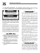
IMPORTANT SAFETY INSTRUCTIONS 15 kW Generator SAVE THESE INSTRUCTIONS – The manufacturer suggests that these rules for safe operation be copied and posted in potential hazard areas. Safety should be stressed to all operators, potential operators, service and repair technicians for this equipment. WARNING: The engine exhaust from this product contains chemicals known to the state of California to cause cancer, birth defects or other reproductive harm.
IMPORTANT SAFETY INSTRUCTIONS 15 kW Generator • • • • • be done around an operating unit, stand on an insulated, dry surface to reduce shock hazard. Do not handle any kind of electrical device while standing in water, while barefoot, or while hands or feet are wet. DANGEROUS ELECTRICAL SHOCK MAY RESULT. The National Electrical Code (NEC) requires the frame and external electrically conductive parts of the generator to be connected to an approved earth ground.
Section 1 — General Information 15 kW Generator DANGER qualified electricians or contractors should Only attempt such installations, which must comply strictly with applicable codes, standards and regulations. 1.1 UNPACKING/INSPECTION After unpacking, carefully inspect the contents for damage. • This standby generator set has been factory supplied with a weather protective enclosure that is intended for outdoor installation only.
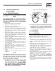
Section 1 — General Information 15 kW Generator 1.5 THE GENERATOR Figure 1.
Section 1 — General Information 15 kW Generator 1.6 SPECIFICATIONS 1.6.1 GENERATOR Rated Max. Cont. Power Capacity (Watts*) ..... 13,000 NG/ 15,000 LP† Rated Voltage....................................................... 120/240 Rated Max. Continuous Load Current (Amps) 120 Volts + ......................................108.3 NG/125.0 LP 240 Volts ..............................................54.2 NG/62.5 LP Main Line Circuit Breaker....................................65 Amp Phase ......................
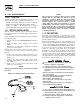
Section 1 — General Information 15 kW Generator 1.9 RECONFIGURING THE FUEL SYSTEM Figure 1.2 - Demand Regulator OUTLET PORTS FUEL HOSE 1.9.1 15KW, 990CC ENGINES To reconfigure the fuel system from NG to LP, follow these steps: NOTE: BRASS HOSE FITTING IDLE CIRCUIT PORT U T 1 TAP 1/8 NPT BRASS HOSE FITTING REGULATOR HOUSING PORT ADJUSTER SCREWS The primary regulator for the propane supply is NOT INCLUDED with the generator. A fuel pressure of 11 to 14 inches of water column (0.4 to 0.
Section 1 — General Information 15 kW Generator 1.10.2 TRANSFER SWITCH 1.10.2.1 15 kW Units Transfer switches for use with this generator are sold separately and can be purchased from dealers. • Install any transfer switch in accordance with the instructions supplied with the transfer switch. • Failure to utilize a the manufacturer’s transfer switch with this generator will void the warranty. 1.
Section 2 — Post Installation Start-up and Adjustments 15 kW Generator The following procedures are to be observed: • Wear full eye protection and protective clothing; • Where electrolyte contacts the skin, wash it off immediately with water; • Where electrolyte contacts the eyes, immediately flush thoroughly with water and seek medical attention; and • Spilled electrolyte is to be washed down with an acid neutralizing agent.
Section 2 — Post Installation Start-up and Adjustments 15 kW Generator DANGER with caution! Generator power voltage Proceed is now supplied to the transfer switch. Contact with live transfer switch parts will result in dangerous and possibly fatal electrical shock. 11. Connect an accurate AC voltmeter and a frequency meter across transfer switch terminal lugs E1 and E2. Voltage should be 242-252 volts; frequency should read about 61-63 Hertz. 12.
Section 2 — Post Installation Start-up and Adjustments 15 kW Generator With the generator running and loads powered by generator AC output, turn ON the utility power supply to the transfer switch. The following should occur: • After about six seconds, the switch should transfer loads back to the utility power source. • About one minute after retransfer, the engine should shut down. 2.
Section 3 — Operation 15 kW Generator 2.7 ENGINE GOVERNOR ADJUSTMENT If both AC frequency and voltage are correspondingly high or low, adjust the engine governor as follows: 2.7.1 15 KW UNITS 1. Loosen governor clamp bolt (See Figure 2.3). Figure 2.3 — V-twin Engine Governor Adjustment 2.8 VOLTAGE REGULATOR ADJUSTMENT With the frequency between 62-63.5 Hertz, slowly turn the slotted potentiometer (Figure 2.5) until line voltage reads 244-252 volts.
Section 3 — Operation 15 kW Generator 9. Allow the unit to cool. 10. Set the generator’s main circuit breaker to its OFF (or OPEN) position. 11. Set the generator's AUTO/OFF/MANUAL switch to OFF. Remove the 7.5A and 15A fuses from the generator control panel. Disconnect the battery cables as outlined in “General Hazards” (page 2). 12. Drain the oil and remove the oil filter. Replace the oil filter according to Section 3.4, “Changing the Oil Filter”.
Section 3 — Operation 15 kW Generator 3.3.2 120 VAC GFCI OUTLET The generator is equipped with an external 15 amp, 120 volt, GFCI convenience outlet that is located in the right rear of the generator enclosure. When the generator is running, in the absence of utility power, this outlet may be used to power items outside a home such as lights or power tools. This outlet may also be used when utility power is present by running the generator in manual mode.
Section 3 — Operation 15 kW Generator 5. To crank and start the engine, set the AUTO/OFF/ MANUAL switch to MANUAL. 6. Let the engine stabilize and warm up for a few minutes. 7. Set the generator’s main circuit breaker to its ON (or CLOSED) position. The standby power source now powers the loads. 3.5.2 TRANSFER BACK TO UTILITY POWER SOURCE When utility power has been restored, transfer back to that source and shut down the generator. This can be accomplished as follows: 1.
Section 4 — Maintenance 15 kW Generator 3.7.3 4.2 OVERCRANK This feature prevents the generator from damaging itself when it continually attempts to start and another problem, such as no fuel supply, prevents it from starting. The unit will crank and rest for a preset time limit. Then, it will stop cranking, and the LED will light indicating an overcrank failure. The AUTO/OFF/ MANUAL switch will need to be set to OFF and then back to AUTO to reset the generator control board.
Section 4 — Maintenance 15 kW Generator 4.5 attempt to crank or start the engine before Any it has been properly serviced with the recommended oil may result in an engine failure. 4.3.2 OIL CHANGE PROCEDURE To change the oil, proceed as follows: 1. Run the engine until it is thoroughly warmed up then shut OFF the engine. 2. Immediately after the engine shuts OFF, pull the oil drain hose (Figure 4.3) free of its retaining clip. Remove the cap from the hose and drain the oil into a suitable container.
Section 4 — Maintenance 15 kW Generator Figure 4.5 – Setting the Spark Plug Gap SET PLUG GAP AT 0.050 mm/0.020 inch 4.7 BATTERY MAINTENANCE • Wear full eye protection and protective clothing; • Where electrolyte contacts the skin, wash it off immediately with water; • Where electrolyte contacts the eyes, immediately flush thoroughly with water and seek medical attention; and • Spilled electrolyte is to be washed down with an acid neutralizing agent.
Section 4 — Maintenance 15 kW Generator • Make sure the piston is at Top Dead Center (TDC) of its compression stroke (both valves closed). To get the piston at TDC, remove the intake screen at the front of the engine to gain access to the flywheel nut. Use a large socket and socket wrench to rotate the nut and hence the engine. While watching the piston through the spark plug hole. The piston should move up and down. The piston is at TDC when it is up as high as it can go. • Loosen the rocker jam nut.
Section 4 — Maintenance 15 kW Generator 4.12 OUT OF SERVICE PROCEDURE 4.12.2 RETURN TO SERVICE 4.12.1 REMOVAL FROM SERVICE To return the unit to service after storage, proceed as follows: If the generator cannot be exercised every seven days, and will be out of service longer than 90 days, prepare the generator for storage as follows: 1. Start the engine and let it warm up. 2. Close the fuel shutoff valve in the fuel supply line and allow the unit to shut down. 3.
Section 4 — Maintenance 15 kW Generator 4.13 SERVICE SCHEDULE ATTENTION: It is recommended that all service work be performed by the nearest dealer. SYSTEM/COMPONENT X = Action R = Replace as Necessary * = Notify Dealer if Repair is Needed.
Section 5 — Troubleshooting 15 kW Generator 5.1 TROUBLESHOOTING GUIDE Problem Cause Correction The engine will not crank. 1. Fuse blown 1. Replace 15A fuse on generator control panel. 2. Tighten, clean or replace as necessary. 3. * 4. * 5. Charge or replace battery. 2. Loose, corroded or defective battery cables 3. Defective starter contactor (7 kW) 4. Defective starter motor 5. Dead Battery The engine cranks but will not start. The engine starts hard and runs rough. 1. Out of fuel 2.
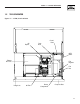
716 [28 743 [29 M6PEM M6P M6PEM-T PE T LEFT SIDE VIEW 622 [24.5"] 604 [23.5"] 76.2mm [3.00"] PEA GRAVEL MINUMUM 704 [27.7"] 207 [8.14"] TRANSFER SWITCH (IF SUPPLIED) 308 [12"] FRONT VIEW 1232 [48.5"] 1193 [47"] "DO NOT LIFT BY THE ROOF" LIFTING HOLES 4-CORNERS Ø30.2mm [Ø1.19"] 149 [5.9"] RIGHT SIDE VIEW 490.7 [ AIR 260 [10.2"] **ALL DIMENSIONS IN: MILLIMETERS [INCHES] REAR VIEW ROUNDING LUG CABLE ACCESS HOLES.
Section 7 — Electrical Data 15 kW Generator Wiring Diagram – Drawing No. 0E9016 ENGINE WIRING 3 2 1 DIAGRAM KEY BA - BRUSH ASSEMBLY BCR - BATTERY CHARGE RELAY CB1 - MAIN OUTPUT BREAKER CB2 - CIRCUIT BREAKER, ALTERNATOR EXCITATION CB3 - CIRCUIT BREAKER, EXTERNAL OUTLET, PUSH/PULL D - DIODE DSW - PCB MOUNTED DIP SWITCH FS - FUEL SOLENOID F1 - FUSE 15 AMP F2 - FUSE 7.
Section 7 — Electrical Data 15 kW Generator Wiring Diagram – Drawing No.
Section 7 — Electrical Data 15 kW Generator Electrical Schematic – Drawing No.
Section 7 — Electrical Data 15 kW Generator Electrical Schematic – Drawing No.
Section 8 — Exploded Views and Parts Lists 15 kW Generator Enclosure – Drawing No.
Section 8 — Exploded Views and Parts Lists 15 kW Generator Enclosure – Drawing No. 0F0080-C ITEM PART NO. QTY.
Section 8 — Exploded Views and Parts Lists 15 kW Generator Control Panel – Drawing No.
Section 8 — Exploded Views and Parts Lists 15 kW Generator Control Panel – Drawing No. 0E9162-J ITEM PART NO. QTY.
32 42 41 40 38 45 44 39 143 37 46 43 29 28 50 52 55 51 26 31 32 3 47 48 49 27 3 140 34 53 30 25 54 56 144 24 23 33 35 36 34 58 57 59 16A 16A 60 18 17 16B 21 22 19 61 63 62 15 66 67 68 69 70 71 72 73 64 20 14 13 65 8 12 11 1 10 2, 5, 19, 20, 39, 40, 47, 64, 93, 140 8, 11, 12, 13 4, 5, 6 16A, 16B, 17, 18 7, 47, 48, 49, 50, 51, 52, 53, 54, 56, 57, 58, 59, 60, 63, 64 47, 48, 49, 50, 51, 52, 53, 54, 56, 57, 58, 59, 60, 62, 63, 64 27, 28, 29 3, 32, 33, 34,
Section 8 — Exploded Views and Parts Lists 15 kW Generator GT-990 Engine – Drawing No. 0F4715-B Part 1 ITEM PART NO. QTY.
Section 8 — Exploded Views and Parts Lists 15 kW Generator GT-990 Engine – Drawing No.
Section 8 — Exploded Views and Parts Lists 15 kW Generator GT-990 Engine – Drawing No. 0F4715-B Part 2 ITEM PART NO. QTY.
36 11 23 5 24 21 43 7 34 33 12 39 13 8 4 6 9 31 17 32 31 28 37 38 40 20 3 14 22 2 15 1 19 10 17 32 10 30 19 32 25 16 24 26 29 36 27 28 18 28 35 36 29 41 28 10 42 32 36 31 41 35 36 Section 8 — Exploded Views and Parts Lists 15 kW Generator 15 kW Generator – Drawing No.
Section 8 — Exploded Views and Parts Lists 15 kW Generator 15 kW Generator – Drawing No. 0D3417-L ITEM 1 2 3 4 5 6 7 8 9 10 11 12 13 14 15 16 17 18 19 20 21 22 23 24 25 26 27 28 29 30 31 32 33 34 35 36 37 38 39 40 41 42 43 PART NO. QTY.
38 12 28 20 21 32 10 25 11 24 23 19 22 17 12 26 28 10 15 14 4 5 13 27 31 11 3 2 16 29 18 17 8 1 26 15 14 13 16 37 9 30 19 22 10 23 29 18 24 11 21 25 12 20 28 Section 8 — Exploded Views and Parts Lists 15 kW Generator Gas Regulator – Drawing No.
Section 8 — Exploded Views and Parts Lists 15 kW Generator Gas Regulator – Drawing No. 0D8720-G ITEM 1 2 3 4 5 8 9 10 11 12 13 14 15 16 17 18 19 20 21 22 23 24 25 26 27 28 29 30 31 32 37 PART NO. 0D5694 0F5022 0C4647 0D4166 0C6070 0F4795 0C5760J 0C6606 097934 0C4645 0C5761 0C5968 0C6066 0C5759 0C5764 0C5764A 070728 0C6069 0C5762 045764 0C6731 0C6067 0C4706 0C6068 0C4643A 026073 026073 0A4032 0D3308 024310 028414A 0D5698A 0D3973 QTY.
Section 9 – Warranty 15 kW Generator NOTE: This Emission Control Warranty Statement pertains to this product only IF the generator size is 15 kW or below. CALIFORNIA AND FEDERAL EMISSION CONTROL WARRANTY STATEMENT YOUR WARRANTY RIGHTS AND OBLIGATIONS The California Air Resources Board (CARB) and the United States Environmental Protection Agency (EPA), together with Generac Power Systems, Inc. (Generac), are pleased to explain the Emission Control System Warranty on your new engine.
Section 9 – Warranty 15 kW Generator EMISSION CONTROL SYSTEM WARRANTY Emission Control System Warranty (ECS Warranty) for 1997 and later model year engines: (a) Applicability: This warranty shall apply to 1997 and later model year engines. The ECS Warranty Period shall begin on the date the new engine or equipment is purchased by/delivered to its original, end-use purchaser/owner and shall continue for 24 consecutive months thereafter.
Section 9 – Warranty 15 kW Generator BRYANT "TWO YEAR" LIMITED WARRANTY FOR "PREPACKAGED EMERGENCY AUTOMATIC STANDBY GENERATORS" For a period of two years from the date of original sale, warrants that its generator will be free from defects in material and workmanship for the items and period set forth below. Bryant will, at its option, repair or replace any part which, upon examination, inspection and testing by a Bryant Dealer, is found to be defective.