Owner’s Manual Air-cooled, Prepackaged Automatic Standby Generators Models: ASPAS1BBA007 (6 kW NG, 7 kW LP) ASPAS1BBA012 (12 kW NG, 12 kW LP) ASPAS1BBA015 (13 kW NG, 15 kW LP) US C LISTED GENERAC R POWER SYSTEMS, INC. R ! Not intended for use as Primary Power in place of utility or in life-support applications. DANGER DEADLY EXHAUST FUMES.
INTRODUCTION Thank you for purchasing this model of the Bryant product line. This model is a compact, high performance, air-cooled, engine-driven generator designed to automatically supply electrical power to operate critical loads during a utility power failure. This unit is factory installed in an all-weather, metal enclosure that is intended exclusively for outdoor installation. This generator will operate using either vapor withdrawn liquid propane (LP) or natural gas (NG).
Table of Contents Bryant Air-cooled 7 kW, 12 kW and 15 kW Generators Introduction ........................Inside Front Cover Section 3 – Maintenance ..............................12 Read This Manual Thoroughly ..............................IFC Contents ................................................................IFC Operation and Maintenance ..................................IFC How to Obtain Service ..........................................IFC 3.1 Fuses ............................................
IMPORTANT SAFETY INSTRUCTIONS Bryant Air-cooled 7 kW, 12 kW and 15 kW Generators SAVE THESE INSTRUCTIONS – The manufacturer suggests that these rules for safe operation be copied and posted near the unit’s installation site. Safety should be stressed to all operators and potential operators of this equipment. ! ! WARNING: ! GENERAL HAZARDS ! ! The engine exhaust from this product contains chemicals known to the state of California to cause cancer, birth defects or other reproductive harm.
IMPORTANT SAFETY INSTRUCTIONS Bryant Air-cooled 7 kW, 12 kW and 15 kW Generators ELECTRICAL HAZARDS • All generators covered by this manual produce dangerous electrical voltages and can cause fatal electrical shock. Utility power delivers extremely high and dangerous voltages to the transfer switch as does the standby generator when it is in operation. Avoid contact with bare wires, terminals, connections, etc., while the unit is running.
Section 1 — General Information Bryant Air-cooled 7 kW, 12 kW and 15 kW Generators DANGER ! 1.1 Only qualified electricians or contractors should attempt such installations, which must comply strictly with applicable codes, standards and regulations. UNPACKING/INSPECTION After unpacking, for damage. carefully inspect the contents • This standby generator set has been factory supplied with a weather protective enclosure that is intended for outdoor installation only.
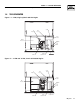
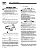
Section 1 — General Information Bryant Air-cooled 7 kW, 12 kW and 15 kW Generators 1.4 THE GENERATOR Figure 1.1 – 7 kW, Single Cylinder GH-410 Engine Oil Dipstick Control Panel Data Decal GFCI Outlet Exhaust Enclosure Fuel Regulator Fuel Inlet Oil Filter Battery Compartment Figure 1.
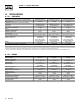
Section 1 — General Information Bryant Air-cooled 7 kW, 12 kW and 15 kW Generators 1.5 SPECIFICATIONS 1.5.1 GENERATOR Model Rated Max. Continuous Power Capacity (Watts*) Rated Voltage Rated Max. Continuous Load Current (Amps) 120 Volts** 240 Volts Main Line Circuit Breaker Phase Number of Rotor Poles Rated AC Frequency Power Factor Recommended Air Filter Battery Requirement (At 0° F -17.
Section 1 — General Information Bryant Air-cooled 7 kW, 12 kW and 15 kW Generators 1.6 SYSTEM SET LED DANGER The “System Set” LED is lit when all of the following conditions are true: 1. The AUTO/OFF/MANUAL switch is set to the AUTO position. 2. The utility voltage being supplied to the unit is being sensed by the PCB. If the utility sense voltage is not connected to the unit or if it is below 168 volts AC, then the system set light will flash rapidly.
Section 1 — General Information Bryant Air-cooled 7 kW, 12 kW and 15 kW Generators 1.11 THE BATTERY If the AUTO/OFF/MANUAL switch is not set to its OFF position, the generator can crank and start as soon as the battery cables are connected. If the utility power supply is not turned off, sparking can occur at the battery posts and cause an explosion. 1.10 BATTERY INSTALLATION Fill the battery with the proper electrolyte fluid if necessary and have the battery fully charged before installing it.
Section 2 — Operation Bryant Air-cooled 7 kW, 12 kW and 15 kW Generators Be sure the utility power supply is turned off and the 7.5A and 15A fuses are removed from the generator control panel, or sparking may occur at the battery posts as the cables are attached and cause an explosion. Servicing of the battery is to be performed or supervised by personnel knowledgeable of batteries and the required precautions. Keep unauthorized personnel away from batteries. 12. Drain the oil and remove the oil filter.
Section 2 — Operation Bryant Air-cooled 7 kW, 12 kW and 15 kW Generators 2.3 AUTOMATIC TRANSFER OPERATION To select automatic operation, do the following: 1. Make sure the transfer switch main contacts are set to their UTILITY position, i.e., loads connected to the utility power source (Figure 2.2). 2. Be sure that normal UTILITY power source voltage is available to transfer switch terminal lugs N1 and N2. 3. Set the generator’s AUTO/OFF/MANUAL switch to AUTO. 4.
Section 2 — Operation Bryant Air-cooled 7 kW, 12 kW and 15 kW Generators 2.5 MANUAL TRANSFER OPERATION 2.5.1 TRANSFER TO GENERATOR POWER SOURCE To start the generator and activate the transfer switch manually, proceed as follows: 1. Set the generator’s AUTO/OFF/MANUAL switch to OFF. 2. Set the generator’s main circuit breaker to its OFF (or open) position. 3. Turn OFF the utility power supply to the transfer switch using the means provided (such as a utility main line circuit breaker).
Section 2 — Operation Bryant Air-cooled 7 kW, 12 kW and 15 kW Generators NOTE: The exerciser will only work in the AUTO mode and will not work unless this procedure is performed. The exerciser will need to be reset every time the 12-volt battery is disconnected and then reconnected. ! The exerciser WILL NOT work if dip switch 2 on the controller printed circuit board (Remote Not Auto) is ON. NOTE: 2.7.
Section 3 — Maintenance Bryant Air-cooled 7 kW, 12 kW and 15 kW Generators Figure 3.3 — Oil Dipstick and Fill, 12 kW and 15 kW Figure 3.1 – Generator Control Panel Oil Dipstick EXTERNAL GFCI OUTLET FUSE 7.5A AUTO OFF MAN. CIRCUIT BREAKER SYSTEM SET LOW OIL 12 VDC HIGH TEMP. SYST OVER SPEED OVER CRANK SET EXERCISE TIME 3.2 MAINTENENANCE ACCESSORY OUTLET 7.
Section 3 — Maintenance MAINTENENANCE Bryant Air-cooled 7 kW, 12 kW and 15 kW Generators Figure 3.4 – Oil Drain Hose and Filter Low Oil Switch Figure 3.5 — 7 kW, Engine Air Cleaner Location High Temp Switch Loos en Air Cleaner Fuel Regulator Screw Oil Drain Hose Oil Filter Figure 3.6 — 12 kW and 15 kW Engine Air Cleaner 3.4 CHANGING THE OIL FILTER Screw Change the engine oil filter as follows: 1. With the oil drained, remove the old oil filter by turning it counterclockwise. 2.
Section 3 — Maintenance Bryant Air-cooled 7 kW, 12 kW and 15 kW Generators Figure 3.7 – Setting the Spark Plug Gap SET PLUG GAP AT 0.76 mm (.030 inch) 7kW 3.7 • Wear full eye protection and protective clothing; • Where electrolyte contacts the skin, wash it off immediately with water; • Where electrolyte contacts the eyes, flush thoroughly and immediately with water and seek medical attention; and • Spilled electrolyte is to be washed down with an acid neutralizing agent.
Section 3 — Maintenance MAINTENENANCE Bryant Air-cooled 7 kW, 12 kW and 15 kW Generators Figure 3.8 – Cooling Vent Locations The exhaust from this product gets extremely hot and remains hot after shutdown. High grass, weeds, brush, leaves, etc. must remain clear of the exhaust. Such materials may ignite and burn from the heat of the exhaust system. 5. Set the AUTO/OFF/MANUAL switch to OFF and turn off the utility power to the transfer switch. Remove the 7.
Section 4 — Service SERVICE Bryant Air-cooled 7 kW, 12 kW and 15 kW Generators 4.1 SERVICE SCHEDULE ATTENTION: It is recommended that all service work be performed by the nearest Bryant Dealer. SYSTEM/COMPONENT X = Action R = Replace as Necessary * = Notify Dealer if Repair is Needed.
Section 5 — Troubleshooting Bryant Air-cooled 7 kW, 12 kW and 15 kW Generators 5.1 TROUBLESHOOTING GUIDE PROBLEM CAUSE CORRECTION The engine will not crank. 1. Fuse blown. 1. Replace 15A fuse in generator control panel. 2. Tighten, clean or replace as necessary. 3. * 4. * 5. Charge or replace battery. 2. Loose, corroded or defective battery cables. 3. Defective starter contactor. (7 kW) 4. Defective starter motor. 5. Dead Battery. The engine cranks but will not start. 1. Out of fuel. 2.
Section 6 — Warranty Bryant Air-cooled 7 kW, 12 kW and 15 kW Generators BRYANT "TWO YEAR" LIMITED WARRANTY FOR "PREPACKAGED EMERGENCY AUTOMATIC STANDBY GENERATORS" For a period of two years from the date of original sale, warrants that its generator will be free from defects in material and workmanship for the items and period set forth below. Bryant will, at its option, repair or replace any part which, upon examination, inspection and testing by a Bryant Dealer, is found to be defective.
Section 6 – Warranty Bryant Air-cooled 7 kW, 12 kW and 15 kW Generators CALIFORNIA EMISSION CONTROL WARRANTY STATEMENT YOUR WARRANTY RIGHTS AND OBLIGATIONS The California Air Resources Board (CARB) and Generac Power Systems, Inc. (Generac) are pleased to explain the Emission Control System Warranty on your new engine.* In California, new utility, and lawn and garden equipment engines must be designed, built and equipped to meet the state’s stringent anti-smog standards.
Section 6 – Warranty Bryant Air-cooled 7 kW, 12 kW and 15 kW Generators EMISSION CONTROL SYSTEM WARRANTY Emission Control System Warranty (ECS Warranty) for 1995 and later model year engines: (a) Applicability: This warranty shall apply to 1995 and later model year engines. The ECS Warranty Period shall begin on the date the new engine or equipment is purchased by/delivered to its original, end-use purchaser/owner and shall continue for 24 consecutive months thereafter.
PART NO. 0F4108 13AS-PA1 REV.A (12/17/04) FORM OM18-1 PRINTED IN U.S.A.