
System information


18-BC53D2-6 23
Example
Use the liquid line temperature and liquid line
gage pressure from Step 2, along with the Dip
Switch setting column, to determine the proper
Liquid Gage Pressure.
STEP 3 - Find the appropriate refrigerant charg-
ing chart on the following page for your system
type and tonnage.
STEP 4 - Locate your liquid line temperature in
the left column of the table and the intersecting
liquid line gage pressure under the DIPSWITCH
selection column.
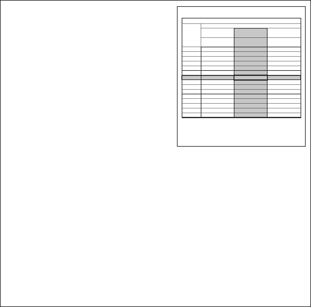
Example:
• A 3 ton AC is installed with line length of 30
feet and a line lift of 15 feet.
• The Dip Switch setting is 2-ON.
• The measured liquid line temperature is
85°F and the Liquid Gage Pressure is 299
PSIG.
299 PSIG is shown as the intersection of the
Dip Switch ON column and the 85°F Liquid
Temperature row.
ONLY DIPSWITCH
1 ON
ONLY DIPSWITCH
2 ON
ONLY DIPSWITCH
3 ON
LOWER * MIDDLE UPPER
55 186 186 190
60 202 202 206
65 219 219 222
70 237 237 240
75 256 256 260
80 277 277 280
85 299 299 302
90 322 322 325
95 346 346 350
100 371 371 375
105 397 397 402
110 425 425 430
115 454 454 460
120 484 484 491
125 515 515 523
PRINTED FROM D155861P02 REV 2
Liquid
Tem
p
(
°F
)
LIQUID GAGE PRESSURE (PSIG)
3 TON AC R410A REFRIGERANT CHARGING CHART
* Data is based on 10.5° of subcooling at a 95° ambient