
System information


18-BC53D2-6 15
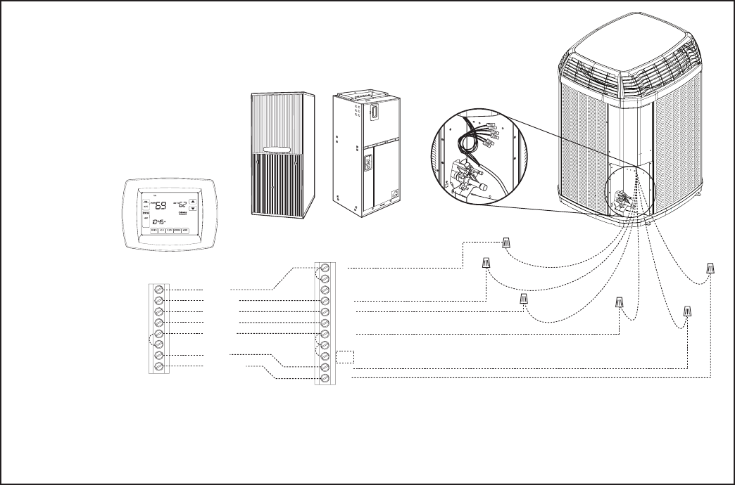
Red
Yellow
Brown
Green
White
Blue
Orange
W1
O
B
X2
G
Y2
Y1
Yellow
Yellow
Brown
Yellow/Red
Blue
Orange
Blue
Black
(X2)
Red
Red
Orange
R
Comfort Control
Comm. Variable Speed
Furnace or Air Handler -
Note 1
Air Conditioner or
Heat Pump -
Note 6
Black
Note 7
W1
W2
W3
G
Y2
B
O
BK
D
Y1
R
Neatly bundle all low voltage
wires behind the service
valve cover as shown.
Notes:
1. See User Interface setup menu for 24 VAC control mode and cooling CFM options.
2. First stage CFM for 4TTZ0 and 4TWZ0 equals 50%.
3. For furnace+heat pump applications, comfort control must be dual fuel capable or use accessory TAYPLUS103A.
4. W3 terminal may not be present on indoor unit.
5. Comfort Control may not have W2 or W3 terminals.
6. Air conditioner models do not use Black (X2) or Orange wires from the outdoor unit.
7. For non-communicating applications, use 24 volt harness accessory BAYACHP024A.
Communicating Indoor Unit
with 24 Volt Control
Hook-up Diagram