
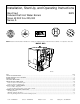
Operating instructions

A new Type B gas vent or flexible liner must be installed in accordance with instructions furnished with vent. Maintain clearances as specified
for vent pipe.
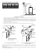
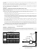
Check vent pipe to see if it is firestopped where it goes through floor or ceiling. It should have an approved vent cap with clearances from roof
shown in Fig. 8. If clearances are less than shown in Fig. 8, have vent checked by local authorities.
For boilers for connection to gas vents or chimneys, vent installations shall be in accordance with Part 7, Venting of Equipment, of the NFGC ANSI
Z223.1-1992 and applicable provisions of local building codes.
Vent connectors serving appliances vented by natural draft shall not be connected into any portion of mechanical draft systems operating under
positive pressure.
PROCEDURE 3—REMOVING EXISTING BOILER FROM COMMON VENTING SYSTEM
When an existing boiler is removed from a common venting system, the common venting system is likely to be too large for proper venting of
the appliances remaining connected to it.
At the time of removal of an existing boiler, the following items shall be followed with each appliance remaining connected to the common venting
system placed in operation, while the other appliances remaining connected to the common venting system are not in operation.
1. Seal any unused openings in the common venting system.
2. Visually inspect the venting system for proper size and horizontal pitch and determine there is no blockage or restriction, leakage, corrosion,
and other deficiencies which could cause an unsafe condition.
3. Insofar as is practical, close all building doors and windows and all doors between the space in which the appliances remaining connected
to the common venting system are located and other spaces of the building. Turn on clothes dryers and any appliances not connected to
the common venting system. Turn on any exhaust fans, such as range hoods and bathroom exhausts, so they will operate at maximum speed.
Do not operate a summer exhaust fan. Close fireplace dampers.
4. Place in operation the appliance being inspected. Follow the lighting instructions. Adjust thermostat so appliance will operate continuously.
5. Test for spillage at the draft hood relief opening after 5 minutes of main burner operation. Use the flame of a match or candle, or smoke
from a cigarette, cigar, or pipe.
6. After it has been determined that each appliance remaining connected to the common venting system properly vents when tested as outlined
above, return doors, windows, exhaust fans, fireplace dampers, and any other gas-burning appliance to their previous conditions of use.
7. Any improper operation of the common venting system should be corrected so the installation conforms with the NFGC ANSI Z223.1-1992.
When resizing any portion of the common venting system, the common venting system should be resized to approach the minimum size
as determined using the appropriate tables in Appendix G in the NFGC ANSI Z223.1-1992.
NOTE: It is recommended that existing gas vents be checked to be sure they meet local codes.
GAS SUPPLY PIPING
PROCEDURE 1—CHECKING GAS SUPPLY
The gas pipe to boiler should run direct from gas meter (or propane regulator). It should supply only the boiler. It must be the correct size for length
of run and boiler rating. See Table 2 for proper size. Be sure gas line complies with local codes and gas company requirements.
The boiler and its individual shutoff valve must be disconnected from gas supply piping system during any pressure testing of gas supply piping
system at test pressures in excess of 0.5 psig (3.5 kPa).
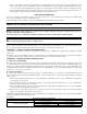
Table 2—Gas Pipe Sizes
NATURAL GAS
Length
of Pipe
(Ft)
Pipe Capacity—Btuh Input
Includes Fittings
1/2 in. 3/4 in. 1 in. 1-1/4 in.
20 92,000 190,000 350,000 625,000
40 63,000 130,000 245,000 445,000
60 50,000 105,000 195,000 365,000
PROPANE GAS
Length
of Pipe
(Ft)
Pipe Capacity—Btuh Input
Includes Fittings
Copper Tubing* Iron Pipe
5/8 in. 3/4 in. 1/2 in. 3/4 in.
20 131,000 216,000 189,000 393,000
40 90,000 145,000 129,000 267,000
60 72,000 121,000 103,000 217,000
* Outside diameter.
The length of pipe or tubing shown should be measured from gas meter or propane
second stage regulator.
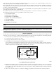
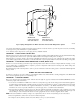
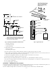
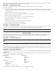
Fig. 9—Gas Piping at Boiler
A95148
MANIFOLD
AUTOMATIC
GAS VALVE
MANUAL
SHUT-OFF
VALVE
SEDIMENT TRAP
FLOOR LINE
GROUND JOINT
UNION
—9—