
Operating instructions

INSTALLATION—SYSTEM PIPING
1. Place boiler in selected location (as near chimney as possible). Boiler is shipped assembled. Only the relief valve with a drain line to carry
any water to a drain and a drain valve need to be installed.
2. Install relief valve on 3/4-in. pipe nipple in tapped opening in left end section. Connect a drain line of same pipe size (3/4 in.) to carry any
water away to a drain. No shutoff of any description shall be placed between safety relief valve and boiler, or on discharge pipes between
such safety valves and the atmosphere. Installation of safety relief valve shall conform to the requirements of the ANSI/ASME Boiler and
Pressure Vessel Code, Section IV.
3. Install drain valve on lower left side of boiler as marked.
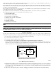
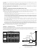
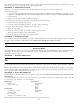
4. Connect supply and return lines to boiler. The connections may require certain additional fittings and parts. (See Fig. 4 and 5.)
If replacing an old boiler with this new one, possibly all that will be required is to connect the existing piping to boiler and install relief valve.
If installing an entire new heating system, first install all radiation units (panels, radiators, or cabinets) and supply and return mains, then make
connections at boiler.
In connecting cold water supply to water valve, make sure that a clean water supply is available. When water supply is from a well or pump, a
sand strainer should be installed at pump.
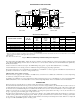
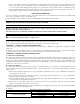
Table 1—Fresh Air Duct Capacities for Ducts Supplying
Fresh Air to Boiler in Tightly Constructed Houses (Btuh)*
FRESH AIR
DUCT SIZE (IN.)
1/4-IN. MESH
SCREEN
WOOD
LOUVERS
METAL
LOUVERS
3X12 144,000 36,000 108,000
8X8 256,000 64,000 192,000
8X12 384,000 96,000 288,000
8-1/2 X 16 512,000 128,000 384,000
* Based on opening covered by 1/4-in. mesh screen, wood louvers, or metal
louvers.
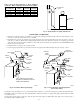
Fig. 3—Fresh Air Duct for Tightly Sealed House
A95141
BOILER
FRESH AIR
DUCT
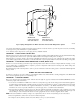
Fig. 4—Forced Hot Water Typical Piping
A95176
SUPPLY
MAIN
AIR
PURGER
FILTROL
TANK
LIMIT
CONTROL
RETURN
LINE
2 IN. CLEARANCE MUST BE KEPT
BETWEEN SYSTEM PIPING AND ANY
COMBUSTIBLE MATERIAL
RELIEF
VALVE
COLD WATER
INLET
AIR VENT
GAUGE
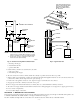
Fig. 5—Forced Hot Water Typical Piping with
Zone Control Valves
A95194
AIR
PURGER
FILTROL
TANK
LIMIT
CONTROL
RETURN
LINE
RELIEF
VALVE
COLD
WATER
INLET
AIR VENT
GAUGE
ELECTRIC
ZONE
VALVES
TO ZONE 1
SUPPLY MAIN
TO ZONE
2 SUPPLY
MAIN
—6—