
Operating instructions

10. After visually inspecting flame, replace lower front panel.
WARNING: If appliance will not operate after several tries, turn gas control knob to OFF position and call your service
technician or gas supplier.
B. To Turn Off Gas To Appliance
1. Set thermostat to lowest setting.
2. Turn off all electric power to appliance if service is to be performed.
3. Push in gas control knob slightly and turn clockwise to OFF position. Do not force.
CHECKING AND ADJUSTING
PROCEDURE 1—GAS VALVE SAFETY SHUTDOWN TEST
With main burners firing, disconnect ignition cable from intermittent pilot control box. Gas valve should shut off main burners. TURN OFF
ELECTRIC POWER to boiler before reconnecting ignition cable to prevent electric shock.
PROCEDURE 2—PILOT BURNER ADJUSTMENT
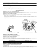
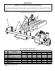
Pilot flame should surround 3/8- to 1/2-in. of pilot sensor. (See Fig. 12.) If flame needs adjusting, proceed as follows:
1. Remove screw cover over pilot adjusting screw.
2. Insert small screwdriver and adjust flame as needed. (See Fig. 12.) Turn screw counterclockwise to increase flame and clockwise to decrease
flame. (See Fig. 13.)
3. Replace screw cover over pilot adjusting screw.
PROCEDURE 3—MAIN BURNER AIR ADJUSTMENT
The stainless steel main burners do not require primary air adjustment.
PROCEDURE 4—LIMIT CONTROLS ADJUSTMENT
Instructions for each control are included with controls.
Table 3 shows recommended boiler water temperatures. These settings can be changed after becoming familiar with how system works. For
example, if system is not giving quite enough heat in very cold weather, the limit setting can be raised to 220°F.
PROCEDURE 5—THERMOSTAT HEAT ANTICIPATOR ADJUSTMENT
Instructions for final adjustment of thermostat are packaged with thermostat.
Set heat anticipator at 0.2.
Check thermostat operation. When set above temperature indicated on thermometer, boiler burners should ignite. Make certain thermostat shuts
boiler off when room temperature reaches selected setting and starts boiler operating when room temperature falls a few degrees.
Fig. 12—Pilot Flame and Sensor
A95160
3
⁄8″ to
1
⁄2″
FLAME
ON SENSOR
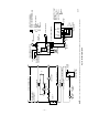
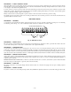
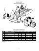
Fig. 13—Automatic Gas Valve
A95201
OFF
ON
GAS CONTROL KNOB
PRESSURE
REGULATOR
ADJUSTMENT
(UNDER CAP SCREW)
PILOT ADJUSTMENT
(UNDER CAP SCREW) PILOT OUTLET
GROUND
TERMINALS (2)
WIRING
TERMINALS (3)
OUTLET PRESSURE TAP
INLET
PRESSURE TAP
INLET
OUTLET
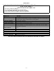
Table 3—Recommended Boiler Water Temperatures
TYPE OF HEATING UNIT LIMIT CONTROL SETTING
Standing Radiators 180°F
Baseboard and Convector Radiators 200°F
—15—