Installation, Start-Up, and Operating Instructions Gas-Fired Induced-Draft Hot Water Boilers Sizes 42,500 thru 225,000 Series A CANADIAN GAS ASSOCIATION ® A PP R O VED BW3 ama R ® ASME NOTE: Read the entire instruction manual before starting the installation. These instructions must be affixed on or adjacent to the boiler. MODEL BW3 A89453 Index Page SAFETY CONSIDERATIONS..............................................................................................................................
GAS SUPPLY PIPING ............................................................................................................................................................................................9-10 Checking Gas Supply ..........................................................................................................................................................................................9-10 Connecting Gas Piping ....................................................................
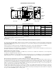
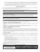
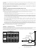
BOILER RATINGS AND CAPACITIES 1 1⁄4″ SUPPLY A RELIEF VALVE 23 1⁄4″ COMBINATION LIMIT & RELAY CONTROL TEMP PRESSURE GAGE VENT CONNECTOR 1 1⁄4″ RETURN BLOWER 29″ 25 1⁄4″ 23″ 5 5⁄8″ 5 1 3⁄4″ BURNER LEFT SIDE PRESSURE SWITCH 5⁄8″ 3⁄8″ 7 8 1⁄2″ GAS VALVE FRONT CIRCULATOR INT. PILOT CONTROL RIGHT SIDE A85084 Gas-Fired Hot Water Boilers BOILER MODEL NUMBER* BW3AA-000042AAAA BW3AA-000075AAAA BW3AA-000112AAAA BW3AA-000150AAAA BW3AA-000187AAAA BW3AA-000225AAAA NO.
Where required by authority having jurisdiction, the installation must conform to American Society of Mechanical Engineers Safety Code for Controls and Safety Devices for Automatically Fired Boilers, No. CSD-1. Before installing the boiler in the United States, refer to the current edition of the NFGC. For further information, the NFGC is available from National Fire Protection Association Inc.
7. The floor supporting boiler must be non-combustible. If it is combustible, place the boiler on a factory-approved combustible floor base. We use a 2-in. cladite™ pad as a combustible floor base. These are available from your local supplier. Use a minimum 24-in. X 30-in. pad for 2-5 section boilers and a minimum 30-in. X 30-in. pad for 6-7 section boilers. The boiler must be centered on combustible floor base. 8.
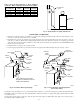
Table 1—Fresh Air Duct Capacities for Ducts Supplying Fresh Air to Boiler in Tightly Constructed Houses (Btuh)* FRESH AIR DUCT SIZE (IN.) 3 X 12 8X8 8 X 12 8-1/2 X 16 1/4-IN. MESH SCREEN 144,000 256,000 384,000 512,000 WOOD LOUVERS 36,000 64,000 96,000 128,000 FRESH AIR DUCT METAL LOUVERS 108,000 192,000 288,000 384,000 * Based on opening covered by 1/4-in. mesh screen, wood louvers, or metal louvers. BOILER A95141 Fig. 3—Fresh Air Duct for Tightly Sealed House INSTALLATION—SYSTEM PIPING 1.
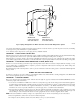
TO SYSTEM A B C D WATER CHILLER VALVES A & B OPEN FOR HEATING; CLOSE FOR COOLING VALVES C & D CLOSE FOR HEATING; OPEN FOR COOLING A95195 Fig. 6—Piping Arrangements for Boiler Used in Connection with Refrigeration System A hot water boiler installed above radiation level must be equipped with a low water cut-off device. A periodic inspection is necessary as is flushing of float-type devices per the manufacturer’s specific instructions. A 2-in.
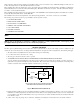
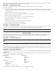
THE VENT PIPE MUST BE AT LEAST 2 FEET HIGHER THAN ANY PART OF THE ROOF WITHIN A 10 FOOT RADIUS OF THE VENT. 10' 2' MIN 3' MIN H VENT HEIGHT D COMMON VENT DIAMETER 6" MINIMUM (NOTE 2) D2 LINER SHEET METAL FIRESTOP CHIMNEY R2 THIMBLE VENT R1 CONNECTOR RISE D1 VENT CONNECTOR DIAMETER HOT WATER HEATER BOILER VENT SYSTEM INSTALL 3 x 4 INCREASER HERE CLEANOUT NOTES: 1. Consult National Fuel Gas Code or New Vent Sizing Tables (A.G.A.) or Venting Tables Category 1 Central Furnaces (G.A.M.
A new Type B gas vent or flexible liner must be installed in accordance with instructions furnished with vent. Maintain clearances as specified for vent pipe. Check vent pipe to see if it is firestopped where it goes through floor or ceiling. It should have an approved vent cap with clearances from roof shown in Fig. 8. If clearances are less than shown in Fig. 8, have vent checked by local authorities.
The boiler must be isolated from gas supply piping system by closing its individual manual shutoff valve during any pressure testing of the gas supply piping system at test pressures equal to or less than 0.5 psig (3.5 kPa). PROCEDURE 2—CONNECTING GAS PIPING Refer to Fig. 9 for general layout at boiler. It shows the basic fittings needed. The gas line enters boiler from right side. The following rules apply: 1.
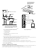
B1 R B 1K2 PRESSURE SWITCH HI LIMIT 3 T DRAFT INDUCER CIRCULATOR 1K ROLLOUT SWITCH INTERMITTENT PILOT CONTROL 24V 5 GND 6 (24V) B2 C2 L2 TO GAS VALVE AT 140C TRANSFORMER 24 V. SECONDARY 120 V. PRIMARY C1 24 V. THERMOSTAT T 24 V. SECONDARY 120 V.
SEQUENCE OF OPERATION 1. Thermostat calls for heat, powering 1K relay coil and closing contacts 1K1 and 1K2. 2. Circulator pump is powered through terminals C1 and C2. 3. Induced draft blower and AT140C transformer primary are powered through terminals B1 and B2. 4. When blower gets up to speed and blower suction pressure reaches pressure switch setpoint, pressure switch contacts close sending 24v to S8600 intermittent pilot control from AT140C transformer secondary. 5.
PROCEDURE 7—DRAIN VALVE This manual valve provides a means of draining all water from boiler and system. It is often installed in the 3/4-in. tapping at bottom of left boiler section. It can also be installed in a tee where return line enters boiler. PROCEDURE 8—WATER TEMPERATURE CONTROL The water temperature limit control in relay is adjustable and may be set as necessary. It may be set as low as 140°F or as high as 240°F. Setting depends on type and amount of radiation involved and weather conditions.
FOR YOUR SAFETY READ BEFORE OPERATING WARNING: If you do not follow these instructions exactly, a fire or explosion may result causing property damage, personal injury, or loss of life. This appliance is equipped with an ignition device which automatically lights burner. Do NOT try to light burner by hand. BEFORE OPERATING, smell all around appliance area for gas. Be sure to smell next to the floor because some gas is heavier than air and will settle on the floor.
10. After visually inspecting flame, replace lower front panel. WARNING: If appliance will not operate after several tries, turn gas control knob to OFF position and call your service technician or gas supplier. B. To Turn Off Gas To Appliance 1. Set thermostat to lowest setting. 2. Turn off all electric power to appliance if service is to be performed. 3. Push in gas control knob slightly and turn clockwise to OFF position. Do not force.
PROCEDURE 6—SAFETY CONTROLS CHECK After setting limit control to desired setting, check to see if it shuts off gas supply to burners. Turn thermostat to call for heat and let boiler run until temperature of water reaches limit setting. Gas valve should shut off and circulator should keep running until thermostat is satisfied or water cools enough to restart burners through limit control.
PROCEDURE 7—CLEANING BOILER AND BURNERS Flue passages between sections should be examined yearly and cleaned if necessary. To clean: 1. Remove burners, pilot, and vent pipe. 2. Remove top and front jacket panels. 3. Split silicone seal on flue collector and cleanout plates with a razor blade. 4. Remove flue collector. 5. Remove cleanout plates by tapping upwards on bottom of plate with a hammer. 6. Remove loose silicone sealant from sections, flue collector, and cleanout plates. 7.
SERVICE HINTS You may avoid inconvenience and service calls by checking these points before you call for service. FOR YOUR SAFETY WHAT TO DO IF YOU SMELL GAS 1. 2. 3. 4. Do not try to light any appliance. Do not touch any electric switch; do not use the phone. Leave the building immediately, then call your gas supplier. If you cannot reach the gas supplier, call the fire department.
REPAIR PARTS IMPORTANT — READ THESE INSTRUCTIONS BEFORE ORDERING All parts listed in the following Parts List may be ordered through your nearest supplier or direct from the factory. When ordering parts, first obtain the Model No. from the data plate on boiler, then determine the Part No. (not the Key No.) and the Description of each part from the following illustrations and lists. Be sure to give all this information: The Part No. — The Part Description — The Boiler Model No.
REPAIR PARTS FOR USE WITH PROPANE GAS ONLY 8 3 6 4 5 6A 2 1 A95163 Propane Gas Burners and Manifold Parts KEY NO. 1 2 3 4 5 6 6A 7 8 ‡ This is a Repair Parts List—Not a Packing List PART DESCRIPTION 2 Section 3 Section 4 Section 24-v Gas Valve, Propane Gas 146-62-062 146-62-062 146-62-062 Pilot Tube 146-15-005 146-15-005 146-15-005 10-32 X 3/16-in.
REPAIR PARTS 15 16 14 13 17 12 11 18 3 2 10 7 6 9 8 5 4 19 1 A95202 Jacket—Section and Base Parts 7 8 9 10 11 12 13 14 This is a Repair Parts List—Not a Packing List PART NO.
REPAIR PARTS BOILER CONTROLS AND PIPING 1 3 2 5 6 4 12 13 7 8 11 10 9 A95203 KEY NO. 1 2 3 4 5 6 7A 7B 8 9 10 11 11 12 13 * * * * * * * * * DESCRIPTION 3/4-in. ASME Relief Valve 3/4-in. X 5-1/2-in. Nipple Temperature-Pressure Gage 1-1/4-in. X 5-1/2-in. Nipple 1-1/4-in. X 3/4-in. X 1-1/4-in Tee L8148A Combination Hi Limit and Relay Control Grundfos Pump UP15-42F Taco Pump 007 1-1/4-in. X 2-1/2-in. Nipple 1-1/4-in. Ell 1-1/4-in X 6-in.
SERVICE TRAINING Packaged Service Training programs are an excellent way to increase your knowledge of the equipment discussed in this manual, including: • Unit Familiarization • Maintenance • Installation Overview • Operating Sequence A large selection of product, theory, and skills programs is available, using popular video-based formats and materials. All include video and/or slides, plus companion book.
© 1995 CAC / BDP P.O. Box 70, Indianapolis, IN 46206 imbw3a02 —24— Catalog No.