
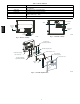
Specifications


8
C07317
Fig. 9 -- Remote Keyed Actuator
C07318
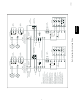
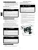
Fig. 10 -- Controller TB3 Connections
4
5 5
4
3
31414
First controller Last controller
Alarm
contacts
Alarm
contacts
Trouble contacts Trouble contacts
EOLR
IDC circuit on
fire alarm
control panel
+
Ð
End-of-line resistor required on
last device for circuit supervision.
Use resistor value specified by the
fire alarm panel manufacturer.
Fire alarm initiating circuit wiring
15
+
Ð
20
Controller
Remote LED indicator
Remote LED indicator wiring
17
6
16
7
9
18
8
Controller
Auxiliary
equipment
Auxiliary
equipment
Auxiliary relay wiring
Power input wiring
Controller
10
B
C
A
24 VAC/DC
120 V
220/240 V
15
19
20
13
3 5
4
1
3
2
2
Alarm
Controller
Remote test station
Alarm
Power
Trouble
Reset/Test
Note: For applications where only the Alarm LED
and Reset/Test switch is required, wiring the
Power LED and Trouble LED is optional.
Remote test station wiring
12
17
16
1
12
1
6
System control,
thermostat, or
power
Fan control
mechanism
17
16
6
System control,
thermostat, or
power
Fan control
mechanism
First
controller
Second
controller
Nexty
controller
Multiple fan shutdown interconnect wiring
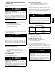
C07319
Fig. 11 -- Typical Smoke Detector Wiring -- Exploded View
HKRNKA