
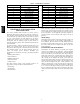
Specifications


3
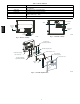
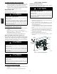
Air is introduced to the duct smoke detector’s sensing chamber
through a sampling tube that extends into the HVAC duct and is
directed back into the ventilation system through an exhaust tube.
The difference in air pressure between the two tubes pulls the
sampled air through the sensing chamber. When a sufficient
amount of smoke is detected in the sensing chamber, the sensor
signals an alarm state and the controller automatically takes the
appropriate action to shut down fans and blowers, change over air
handling systems, notify the fire alarm control panel, etc.
EQUIPMENT DAMAGE HAZARD
Failure to follow this caution may result in damage to
equipment.
Excess temperature differentials between the ambient air and
the sampled air can produce unwanted condensation inside the
sensor, which may cause the sensor to function improperly.
Precautions should be taken to limit the temperature range and
the amount of condensation to which the sensor is exposed.
CAUTION
!
FEATURES
The smoke sensor incorporates the following features:
S Environmental compensation with differential sensing for
reliable, stable, and drift--free sensitivity.
S Magnet--activated test/reset switch on sensors.
S PCB mounted photoelectric sensor with on--board intelligence.
S Cover tamper switch for added security.
S Alarm, Trouble, Dirty, and Power status LEDs. (See Table 1 and
Fig. 2.)
S Extended temperature and air velocity ranges.
S Capable of adding an additional sensors (for a total of two) using
the same controller.
S Multiple operating voltages.
S No tools required to access field connection terminals.
S Recessed momentary switch for test/reset of the detector .
S One set of normally open alarm initiation contacts for
connection to an initiating device circuit on a fire alarm control
panel.
S Two Form--C auxiliary alarm relays for interface with rooftop
unit or other equipment.
S One Form--C supervision (trouble) relay to control the operation
of the Trouble LED on a remote test/reset station.
S Can be wired to up to 14 other duct smoke detectors for multiple
fan shutdown applications.
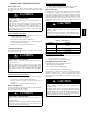
INDICATORS
Normal State
The smoke detector operates in the normal state in the absence of
any trouble conditions and when its sensing chamber is free of
smoke. In the normal state, the Power LED on both the sensor and
the controller are on and all other LEDs are off.
Alarm State
The smoke detector enters the alarm state when the amount of
smoke particulate in the sensor’s sensing chamber exceeds the
alarm threshold value. (See Table 1.) Upon entering the alarm
state:
S The sensor’s Alarm LED and the controller’ s Alarm LED turn
on.
S The contacts on the controller’s two auxiliary relays switch
positions.
S The contacts on the controller’s alarm initiation relay close.
S The controller’s remote alarm LED output is activated (turned
on).
S The controller’ s high impedance multiple fan shutdown control
line is pulled to ground Trouble state.
The SuperDuct duct smoke detector enters the trouble state under
the following conditions:
S A sensor’s cover is removed and 20 minutes pass before it is
properly secured.
S A sensor’s environmental compensation limit is reached (100%
dirty).
S A wiring fault between a sensor and the controller is detected.
An internal sensor fault is detected upon entering the trouble state:
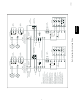
S The contacts on the controller’s supervisory relay switch
positions. (See Fig. 3.)
S If a sensor trouble, the sensor’s Trouble LED the controller’s
Trouble LED turn on.
S If 100% dirty, the sensor’s Dirty LED turns on and the
controller’s Trouble LED flashes continuously.
S If a wiring fault between a sensor and the controller, the
controller’s Trouble LED turns on but not the sensor’s.
NOTE: All troubles are latched by the duct smoke detector. The
trouble condition must be cleared and then the duct smoke detector
must be reset in order to restore it to the normal state.
Multiple Detector Operation
The interconnect feature of the smoke detector allows up to 15
smoke detectors to be connected to each other , typically for
multiple fan shutdown applications. When one of the smoke
detectors goes into alarm, it operates as described above. On the
remaining smoke detectors not in alarm, only the following occurs:
S The auxiliary relay contacts switch positions.
S The remote LED output is activated (turned on).
HKRNKA