
Instruction manual

2. Jumper R and W/W1 thermostat connection on furnace control.
3. Check manifold orifices for gas leaks when main burners ignite. Go to Procedure 4.
4. Adjust gas manifold pressure.
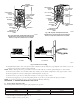
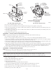
a. Remove caps that conceal adjustment screws for gas-valve regulators. (See Fig. 6C and 6D.)
b. Jumper R, W/W1 thermostat connections on control. (See Fig. 8C or 8D.) Adjust low-heat input rate manifold pressure for propane gas.
(See kit rating plate 327697-204 Rev. B, Fig. 10.) (Note: Gas valve should already have been pre-adjusted, from prior steps for two-stage
gas valve). Turn low-heat adjusting screw counterclockwise (out) to decrease input rate or clockwise (in) to increase input rate.
c. Jumper R, W/W1 and W2 thermostat connections on control. This keeps furnace in high-heat.
d. Adjust high-heat input rate manifold pressure for propane gas. (See kit rating plate 327697-204 Rev. B, Fig. 10.) Turn high-heat adjusting
screw.
e. Counterclockwise (out) to decrease input rate or clockwise (in) to increase input rate.
f. Main burner flame should be clear blue, almost transparent.
g. Remove jumper across R, W/W1 and W2 after high-heat adjustment.
h. Replace caps that conceal gas-valve-regulator adjustment screws.
5. Turn setup switch LHT (two-stage) or SW-2 (variable speed) switch to OFF position.
6. Turn furnace gas valve switch to OFF.
7. Turn off furnace power supply.
8. Remove manometer and replace manifold pressure tap plug. (See Fig. 6C and 6D.)
NOTE: Use propane-gas-resistant pipe dope to prevent gas leaks. DO NOT use Teflon tape.
9. Turn on furnace power supply.
10. Turn furnace gas valve switch to ON position.
11. Set room thermostat to call for heat.
12. Check pressure tap plug for gas leaks when main burners ignite.
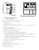
13. When correct input is obtained, main burner flame should be clear blue, almost transparent. (See Fig. 28.)
14. Observe unit operation through 2 complete heating cycles. See sequence of operation in furnace Installation, Start-Up, and Operating
Instructions.
15. Set room thermostat to desired temperature.
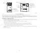
PROCEDURE 8—CHECK LOW GAS PRESSURE SWITCH OPERATION
The newly installed low gas pressure switch is a safety device used to guard against adverse burner operating characteristics that can result from
low gas supply pressure. Switch opens at not less than 6.5″w.c. and closes at not greater than 10.2″w.c.
This switch also prevents operation when the propane tank level is low which can result in gas with a high concentration of impurities, additives,
and residues that have settled to the bottom of the tank. Operation under these conditions can cause harm to the heat exchanger system.
This normally open switch closes when gas is supplied to gas valve under normal operating pressure. The closed switch completes control circuit.
Should an interruption or reduction in gas supply occur, the gas pressure at switch drops below low gas pressure switch setting, and switch opens.
Any interruption in control circuit (in which low gas pressure switch is wired) quickly closes gas valve and stops gas flow to burners.
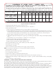
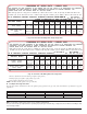
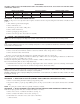
→ Fig. 10—Conversion Kit Rating Plate
A04118
CONVERSION KIT RATING PLATE - CARRIER CORP.
THIS APPLIANCE HAS BEEN CONVERTED TO USE PROPANE GAS FOR FUEL. REFER TO KIT INSTRUCTIONS FOR CONVERSION
PROCEDURES. USE PARTS SUPPLIED BY CARRIER CORPORATION AND INSTALLED BY QUALIFIED PERSONNEL. SEE
EXISTING RATING PLATE FOR APPLIANCE MODEL NO. AND INPUT RATING.
NOTE: Furnace gas input rate on rating plate is for installations up to 2000 ft above sea level. In U.S.A. the input rating for altitudes above 2000 ft must
be derated by 4% for each 1000 ft above sea level. In Canada the input rating must be derated by 10% for altitudes of 2000 ft to 4500 ft above sea level.
FUEL USED: PROPANE GAS
INLET PRESSURE (min - max): 11.0 - 13.6 in. wc
ALTITUDE OF INSTALLATION (FT. ABOVE SEA LEVEL) U.S.A. *
APPLIANCE MODELS
0 2001 * 3001 4001 5001 6001 7001 8001 9001
to 2000 to 3000 to 4000 to 5000 to 6000 to 7000 to 8000 to 9000 to 10000
310AAV, 310JAV, 311AAV,
311JAV, 58STA, 58STX,
58DLA, 58DLX, PG8MAA,
PG8JAA
Orifice No.
55
1.30mm
1.25mm 1.25mm
1.25mm
56 56 56
Mnfld Press
11.0 11.0 10.5
11.0
11.0 10.5
11.0
11.0 10.5
Orifice No.
55 1.30mm 1.30mm 1.25mm 56 56 56
Mnfld Press
11.0 / 11.0 / 10.5 / 11.0 / 11.0 / 10.5 / 11.0 / 11.0 / 10.5 /
312AAV, 312JAV, 315AAV,
315JAV, 58CTA, 58CTX,
58CVA, 58CVX,
High / Low
5.8 5.3 5.0 5.5 5.2 4.9 5.7 5.2 4.8
* For Canadian Installations from 2000 to 4500 ft use U.S.A. column 2001 to 3000 ft.
327697-204 REV. B
1.30mm
1.25mm
1.25mm
KIT NO. KGANP3001ALL (SUPERSEDES: KGANP2701LPS, KGANP2801F80, )KGANP2901ALL
—11—