
Instruction manual

2. Cut wire tie on loop in furnace wires attached to J-Box.
3. Move box to desired location.
4. Fasten J-Box to casing with two screws removed in Step 1.
5. Route J-Box wires within furnace away from sharp edges,
rotating parts, and hot surfaces.
ELECTRICAL CONNECTION TO J-BOX
Field-Supplied Electrical Box on Furnace J-Box Bracket
See Fig. 23.
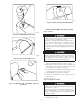
1. Remove cover from furnace J-Box.
2. Attach electrical box to furnace J-Box bracket with at least
two field-supplied screws through holes in electrical box into
holes in bracket. Use blunt-nose screws that will not pierce
wire insulation.
3. Route furnace power wires through holes in electrical box and
J-Box bracket, and make field-wire connections in electrical
box. Use best practices (NEC in U.S. and CSA C22.1 in
Canada) for wire bushings, strain relief, etc.
4. Route and secure field ground wire to green ground screw on
J-Box bracket.
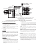
5. Connect line voltage leads as shown in Fig. 25.
6. Reinstall cover to J-Box. Do not pinch wires between cover
and bracket.
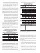
→ Table 7—Electrical Data
FURNACE SIZE
VOLTS-
HERTZ-
PHASE
OPERATING
VOLTAGE RANGE
MAXIMUM
UNIT AMPS
UNIT
AMPACITY#
MAXIMUM
WIRE LENGTH (FT)‡
MAXIMUM
FUSE OR CKT BKR
AMPS†
MINIMUM
WIRE GAUGE
Maximum* Minimum*
045-08/024045 115-60-1 127 104 5.4 7.54 49 15 14
045-12/036045 115-60-1 127 104 7.0 9.50 39 15 14
070-08/024070 115-60-1 127 104 5.0 7.06 52 15 14
070-12/036070 115-60-1 127 104 6.8 9.22 40 15 14
070-16/048070 115-60-1 127 104 9.5 12.60 29 15 14
090-14/042090 115-60-1 127 104 8.2 10.83 34 15 14
090-16/048090 115-60-1 127 104 10.0 13.13 28 15 14
090-20/060090 115-60-1 127 104 13.6 17.61 32 20 12
110-12/036110 115-60-1 127 104 8.2 10.75 34 15 14
110-16/048110 115-60-1 127 104 10.1 13.12 28 15 14
110-22/066110 115-60-1 127 104 14.8 18.99 30 20 12
135-16/048135 115-60-1 127 104 10.2 13.27 27 15 14
135-22/066135 115-60-1 127 104 14.4 18.55 30 20 12
155-20/060155 115-60-1 127 104 15.0 19.33 29 20 12
* Permissible limits of the voltage range at which the unit operates satisfactorily.
# Unit ampacity = 125 percent of largest operating component’s full load amps plus 100 percent of all other potential operating components’ (EAC, humidifier, etc.) full load
amps.
† Time-delay type is recommended.
‡ Length shown is as measured 1 way along wire path between unit and service panel for maximum 2 percent voltage drop.
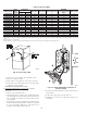
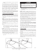
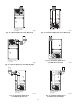
Fig. 22—Relocating J-Box
A02099
TWO
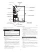
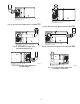
→ Fig. 23—Field-Supplied Electrical Box on
Furnace Casing
A03221
20
→